ADC3-60M
Analog-to-digital converter
Last updated
Analog-to-digital converter
Last updated
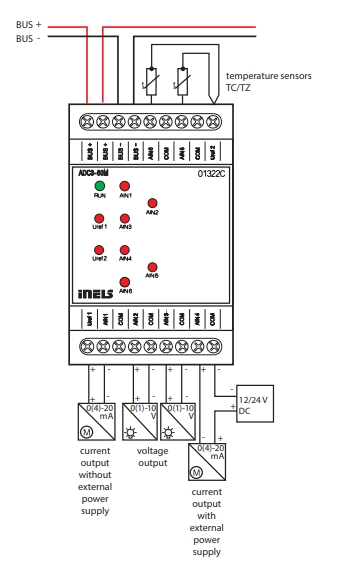
Provide an overview of this product design and usage. Includes circuit diagrams, terminal details, etc.,
Analog Inputs: Equipped with 6 analog inputs for connecting temperature sensors or analog sensors generating current or voltage signals.
Resolution: Analog inputs feature a resolution of a 14-bit AD converter, ensuring precise measurement accuracy.
Common Terminal: Analog inputs share a common terminal, labeled as COM.
Configuration Flexibility: Analog inputs/outputs can be independently configured in iDM3 as voltage (U), current (I), or temperature.
Recommended Clima Sensor: Clima sensor recommended as a meteorological station, available in FOUR types with five to eight outputs. Offers measurements including rainfall, brightness, twilight, wind speed, temperature, and relative humidity.
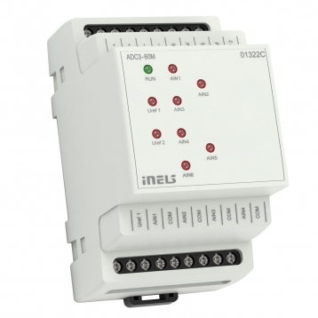
LED Indicators: Red LEDs on the front panel indicate exceeding the range, sensor interruption, or overload of Uref output, ensuring quick diagnostics.
Temperature Inputs: Temperature inputs at the top of the terminal are used to connect temperature sensors such as TC and TZ.
Modular Design: ADC3-60M 3-MODULE version designed for mounting into a switchboard on DIN rail EN60715, facilitating standardized installation.
The chart illustrates the compatibility between converter and various central units, firmware versions, and integration options.
1
CU3-01M
01.3A.00
NA
NA
2
CU3-02M
01.3A.00
NA
NA
3
CU3-07M
01.3A.00
Yes
Yes
4
CU3-08M
01.3A.00
Yes
Yes
6
CU3-09M
Preparation
Preparation
Preparation
7
CU3-10M
Preparation
Preparation
Preparation
Introduction
iNELS Design Manager, or IDM3, is for programming iNELS units. This software serves as the platform for configuring device parameters, defining functions, and executing the programming required for iNELS units.
Device parameters, such as sensor range and thresholds, backlights, and operational modes, can be easily adjusted within the IDM3.
The process of programming in IDM3 typically involves defining functions and establishing logical connections between different devices. This allows for the creation of automation scenarios and the implementation of intelligent control strategies.
Starting up
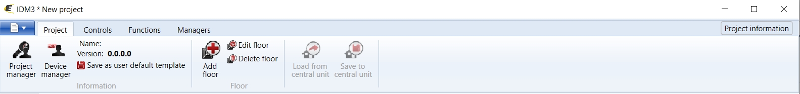
Select the "blue control icon" as shown in Fig 1 > Clicking on the option "New project from default template“ allows you to create a new project from a predefined template.
Select the "Device manager" (Fig 1)> Add "New unit "> Select the central unit > Add "New unit">Select the "Internal-Master/ BUS"> Add "New unit "> Add the devices> Click on the devices to see the "Parameters".
Parameters:
Parameters in the iNELS devices refer to the measurable factors or characteristics that define the behavior or performance of the device. These could include electrical properties, physical dimensions, environmental conditions, and various other specifications depending on the type of device.
These are settings specific to individual devices within your automation system.
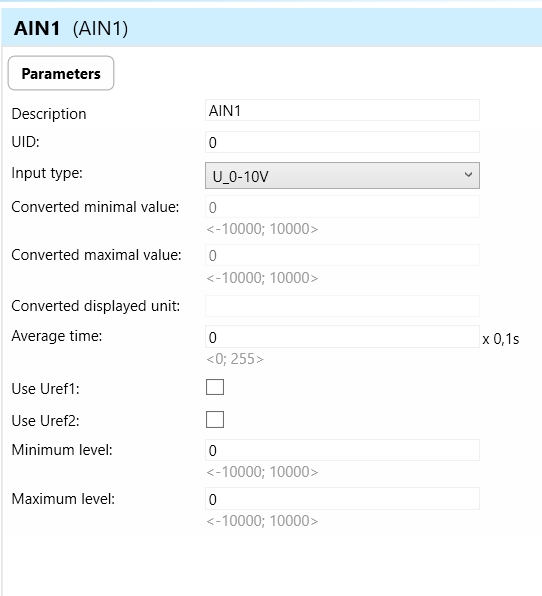
The specific parameters of the ADC3-60M in the iDM as shown in Fig.2
Clicking on the ACD3-60M (Fig.2), will navigate to selected firmware, unit address, name, and description, along with other parameters as described below :
It is important to add the device address for proper communication with the unit. The Hexadecimal device address can be find from the device.
ADC3-60M Analog-to-Digital Converter Parameters:
Uref 1,2 Switch: Uref 1,2 Switch is a parameter indicating the switch position for Uref 1 and Uref 2. It determines the reference voltage source for the analog inputs.
Uref 1,2 High level: Uref 1,2 High level represents the high-level threshold for Uref 1 and Uref 2. It defines the upper limit of the reference voltage range used for analog input conversion.
AIN1-6 (Analog Inputs 1-6): AIN1-6 represent the six analog input channels available on the ADC3-60M. These channels are used to connect temperature sensors or analog sensors generating current or voltage signals.
Input Type: Specifies the type of input signal being measured by each analog input channel (e.g., voltage, current, temperature, ). The different types of input are shown in the figure below.
Converted Minimal Value: Indicates the minimum value that can be accurately measured and converted by the ADC for each analog input channel.
Converted Maximum Value: Denotes the maximum value that can be accurately measured and converted by the ADC for each analog input channel.
Converted Displayed Unit: Specifies the unit of measurement used to display the converted values from each analog input channel (e.g., degrees Celsius for temperature, volts for voltage).
Average Time: Defines the time period over which multiple readings are averaged to obtain a stable and accurate measurement for each analog input channel.
Use Uref 1 and Use Uref 2: Determine whether to utilize the reference voltage inputs Uref 1 and Uref 2 for calibration or measurement purposes.
Minimum Level: Sets the minimum allowable threshold for each analog input channel, below which the measured values are considered invalid or below the detection threshold.
Maximum Level: Sets the maximum allowable threshold for each analog input channel, above which the measured values are considered invalid or above the detection threshold.
OUF-Alert 1-6: This parameter serves as an indicator for alert conditions associated with inputs 1 through 6 on the ADC3-60M device. The alert is activated when the switching limit surpasses the configured threshold in any of the inputs. Upon activation, this alert signals users about a fault in one of the inputs, prompting them to investigate and take corrective measures. This is crucial to prevent potential damage to connected loads or the device itself.
OVLO-Alert Uref1-2 (Overvoltage Alert for Uref1-2): OVLO-Alert Uref1-2 parameters denote the alert status for the reference voltage inputs Uref1 and Uref2. These alerts activate when the reference voltage input exceeds its maximum allowable voltage level.
Setting Up Control and Monitoring for iNELS Cloud and iNELS App
It is possible to control and monitor all the bus units in iNELS cloud and iNELS app. There are two stages to set up this function. Stage one is to do configuration in iDM3 and stage 2 is to do Configuration in iNELS cloud page and iNELS app.
1. Unit and Parameter Selection:
Begin by accessing the iDM3 interface on your PC connected to CU. Navigate to the Device Manager section and carefully select the units and parameters you wish to control. This step is essential for determining what gets exported to the iNELS cloud and app.
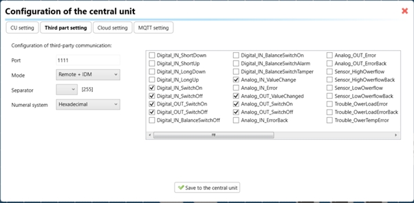
2. CU Configuration and Third-Party Settings :
After the above step, go to the CU configuration in the iDM3, and select the page for third-party settings.
Inside the third-party settings page, designate the port for cloud connection. Set the mode of operation and choose the numerical system as hexadecimal. Pay close attention to verifying and configuring all essential parameters for successful cloud export.
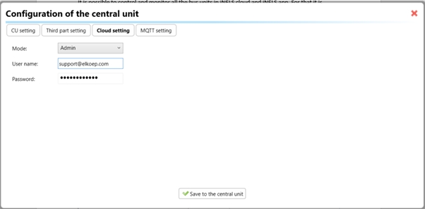
3. Cloud Settings:
Move on to the Cloud Settings section within iDM3.
Input the details of your iNELS cloud account. If you haven't created one, utilize the "New User" tab on the iNELS Cloud web page to establish a free account. (Inels Cloud - ElkoEP).
Select the mode and input the cloud account credentials. Save the project to the central unit to generate and store the export project file in the iNELS cloud account.
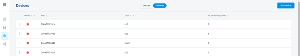
1. Online Status Verification:
Once the cloud credentials and export settings in iDM3 are configured successfully, check the iNELS cloud account's Gateway section. Confirm that the Central Unit (CU) is online and that the export file has been automatically sent to the cloud under your account.
2. Device Creation in Cloud Platform:
In the cloud platform, you have to create new devices in order to control it remotely.
In the device tab, you will find the add device button, which can be used to associate export elements from IDM with the required types and icons.
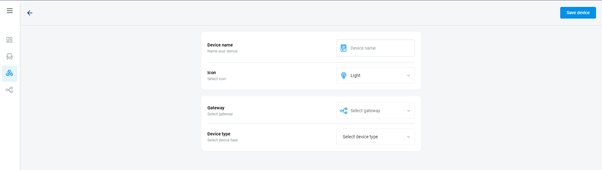
After entering any name of the device, you select the icon, the MAC address of the communication gateway (in this case CU3), a specific type of device and the address of a specific function and element from the iNELS BUS system.
In order to be able to use the iNELS application to control the devices from CU over the local network or the cloud, it is necessary to create a room for bus devices for each central unit and add the devices into the room.
Follow these steps meticulously to ensure a seamless configuration process for controlling and monitoring all bus units through iNELS cloud and iNELS app.
iNELS units support MQTT integration on central units CU3-07M, CU3-08M, CU3-09M, and CU3-10M. It is necessary to select the devices and parameters for 3rd party integration on the device manager in the iDM.
Please note that you have an MQTT broker (local or cloud) running in the installation for this integration.
After you have a working MQTT broker you need to configure iNELS Central units to communicate with it. If you have no knowledge of what MQTT is, you can learn about it from MQTT Essentials articles. https://www.hivemq.com/mqtt/
There is a pre-installed MQTT broker in the iNLES bridge, it can be used to connect the iNELS Central units for integration in your projects.
Configuration in iDM3: Select units of 3rd Party integration.
Unit and Parameter Selection:
Begin by accessing the iDM3 interface on your PC connected to CU. Navigate to the Device Manager section and carefully select the units and parameters you wish to control. This step is essential for determining what gets exported to the 3rd party integration via MQTT.
2. CU Configuration and Third-Party Settings :
After the above step, go to the CU configuration in the iDM3, and select the page for third party settings.
Inside the third-party settings page, designate the port for third-party connection. Set the mode of operation and choose the numerical system as hexadecimal. Pay close attention to verifying and configuring all essential parameters for successful third-party integration.
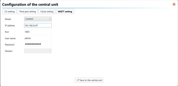
3. MQTT Settings:
Move on to the MQTT Settings section within iDM3.
Input the details of your MQTT broker.
Select the mode and input the broker credentials such as IP, port username and password. Save the project to the central unit.
For MQTT payload description please refer the link below. https://wiki.inels.com/v/inels-bus/3rd-party-integration/mqtt-payload-description-of-inels-bus-devices
Provide any optional, supplementary information that may help in providing a more comprehensive understanding of the product feature