> For the complete documentation index, see [llms.txt](https://wiki.inels.com/llms.txt). Markdown versions of documentation pages are available by appending `.md` to page URLs; this page is available as [Markdown](https://wiki.inels.com/inels-bus/technical-manual-products/detectors/pms3-01.md).
# PMS3-01
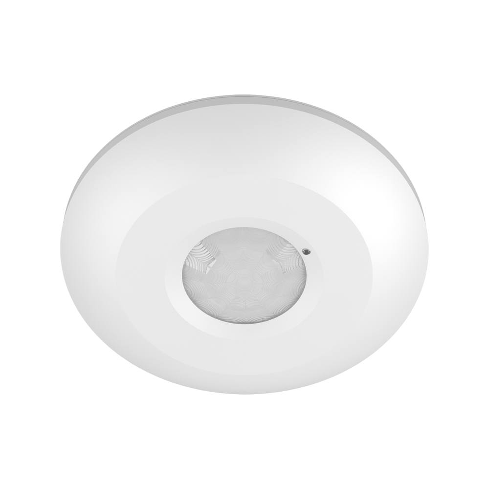
## Overview of devices
{% hint style="info" %}
*An overview of the product design and usage. Also includes circuit diagrams, terminal details, etc.,*
{% endhint %}
Another view
## Key features
**Type and Design:**
The PMS3-01 is a highly versatile and compact motion sensor.
It is designed for ceiling or surface mounting applications.
**Integration and Aesthetics:**
The sensor has an ultra-slim design, facilitating seamless integration into various environments.
Its compact form factor with dimensions of 115 x 24 mm allows for easy installation and integration into different ceiling or surface mounting applications.
**Power Source:**
The sensor is powered by a 27 VDC power source.
It specifically utilizes the iNELS BUS system, ensuring stable and efficient operation.
**Motion Detection Technology:**
The PMS3-01 utilizes infrared technology for precise and reliable motion detection.
**Detection Angle and Range:**
The sensor provides a wide 360-degree detection angle, ensuring comprehensive coverage of the monitored area. The sensor's reach is up to 6m max, allowing flexibility in installation heights ranging from 2.5m to 3.5m, catering to different applications.
**Time Settings:**
The PMS3-01 features a software setting for adjusting time settings.
The time setting can be configured, allowing customization of the sensor's activation duration.
**Operating Conditions:**
The sensor is designed to operate effectively in various environmental conditions. It has a wide working temperature range of -10°C to +40°C, ensuring reliable performance in different settings.
**Integration with iNELS Units:**
The PMS3-01 can be seamlessly integrated and combined with other iNELS units using the iDM3 software. This integration allows for the implementation of additional logic and functions, enabling automation and customized control scenarios based on specific requirements.
## Exemplary circuit diagram/ Wiring Diagram
## Compatibility chart ( CU, minimal FW version and Integration)
*The chart illustrates the compatibility between switching actuator and various central units, firmware versions, and integration options.*
| SL No | Support Central units | Support FW | Support in MQTT | Support in HASS |
| ----- | --------------------- | ----------- | --------------- | --------------- |
| 1 | CU3-01M | 01.02.00 | NA | NA |
| 2 | CU3-02M | 01.02.00 | NA | NA |
| 3 | CU3-07M | 01.02.00 | Yes | NA |
| 4 | CU3-08M | 01.02.00 | Yes | NA |
| 6 | CU3-09M | Preparation | Preparation | Preparation |
| 7 | CU3-10M | Preparation | Preparation | Preparation |
## Programming in iDM
**Introduction**
iNELS Design Manager, or IDM3, is for programming iNELS units. This software serves as the platform for configuring device parameters, defining functions, and executing the programming required for iNELS units.
Device parameters, such as sensor range and thresholds, backlights, and operational modes, can be easily adjusted within the IDM3.
The process of programming in IDM3 typically involves defining functions and establishing logical connections between different devices. This allows for the creation of automation scenarios and the implementation of intelligent control strategies.
**Starting up**
Select the "***blue control icon"*** as shown in ***Fig 1*** > Clicking on the option ***"New project from default template“*** allows you to create a new project from a predefined template.
Select the "***Device manager"*** (***Fig 1***)> Add "***New unit*** "> Select the central unit > Add "***New*** ***unit"***>Select the "***Internal-Master/ BUS">*** Add "***New unit*** "> Add the devices> Click on the devices to see the "***Parameters"***.

***Fig 1: iDM Console***
**Parameters:**
**Parameters** in the iNELS devices refer to the measurable factors or characteristics that define the behavior or performance of the device. These could include electrical properties, physical dimensions, environmental conditions, and various other specifications depending on the type of device.
These are settings specific to individual devices within your automation system.
The specific parameters of the PMS3-01 in the iDM as shown in ***Fig.2***

***Fig.2: Parameters of PMS3-01***
Clicking on the PMS3-014 (***Fig.2***), we can see the selected firmware, address, name, and description, along with other parameters as described below :
**Move-IN**
The **Move-IN** input refers to the motion detection signal that is triggered when the sensor detects movement within its designated range. The parameter controls how the device responds to detected motion and interacts with other connected devices or systems within the iNELS BUS environment.
The **Move-IN** parameter settings shown in the image offer the following configurable options:
1. **Invert Input**:
* This option allows the user to reverse the logic of the motion detection.
* If enabled (checkbox ticked), the sensor will behave in an opposite manner; it will deactivate other actions when motion is detected, and activate when no motion is detected.
* Typically used in specialized automation scenarios.
2. **Split Strictly Long/Short Press**:
* This setting differentiates between long and short motion detections, allowing for more advanced automation control.
* If enabled (checkbox ticked), the system can recognize a short detection (e.g., brief/false motion) versus a long detection (e.g., sustained motion), and trigger different actions accordingly. For instance, a short detection can cause false trigger to turn on a light, to avoid that user can use a long detection that might accurately trigger an event in the system.
## Exports for iNELS Cloud and APP
#### Setting Up Control and Monitoring for iNELS Cloud and iNELS App
It is possible to control and monitor all the bus units in iNELS cloud and iNELS app. There are two stages to set up this function. Stage one is to do configuration in iDM3 and stage 2 is to do Configuration in iNELS cloud page and iNELS app.
#### Configuration in iDM3.
**1. Unit and Parameter Selection:**
Begin by accessing the iDM3 interface on your PC connected to CU. Navigate to the Device Manager section and carefully select the units and parameters you wish to control. This step is essential for determining what gets exported to the iNELS cloud and app.

**2. CU Configuration and Third-Party Settings :**
After the above step, go to the CU configuration in the iDM3, and select the page for third-party settings.
Inside the third-party settings page, designate the port for cloud connection. Set the mode of operation and choose the numerical system as hexadecimal. Pay close attention to verifying and configuring all essential parameters for successful cloud export.

**3. Cloud Settings:**
Move on to the Cloud Settings section within iDM3.
Input the details of your iNELS cloud account. If you haven't created one, utilize the "New User" tab on the iNELS Cloud web page to establish a free account. ([Inels Cloud - ElkoEP](https://inels.cloud/auth/login)).
Select the mode and input the cloud account credentials. Save the project to the central unit to generate and store the export project file in the iNELS cloud account.

#### Configuration in iNELS cloud page and iNELS App.
**1. Online Status Verification:**
Once the cloud credentials and export settings in iDM3 are configured successfully, check the iNELS cloud account's Gateway section. Confirm that the Central Unit (CU) is online and that the export file has been automatically sent to the cloud under your account.

**2. Device Creation in Cloud Platform:**
In the cloud platform, you have to create new devices in order to control it remotely.
In the device tab, you will find the add device button, which can be used to associate export elements from IDM with the required types and icons.

After entering any name of the device, you select the icon, the MAC address of the communication gateway (in this case CU3), a specific type of device and the address of a specific function and element from the iNELS BUS system.
Note: In order to be able to use the iNELS application for communication with CU3 over the local network or the cloud, it is necessary to create a configuration on the website.
Follow these steps meticulously to ensure a seamless configuration process for controlling and monitoring all bus units through iNELS cloud and iNELS app.
## 3rd Party Integration with iNELS BUS
#### 3rd Party Integration (MQTT)
* iNELS units support MQTT integration on central units CU3-07M, CU3-08M, CU3-09M, and CU3-10M. It is necessary to select the devices and parameters for 3rd party integration on the device manager in the iDM.
* Please note that you have an MQTT broker (local or cloud) running in the installation for this integration.
* After you have a working MQTT broker you need to configure iNELS Central units to communicate with it. If you have no knowledge of what MQTT is, you can learn about it from MQTT Essentials articles.
* There is a pre-installed MQTT broker in the iNLES bridge, it can be used to connect the iNELS Central units for integration in your projects.
**Configuration in iDM3: Select units of 3rd Party integration.**
1. **Unit and Parameter Selection:**
Begin by accessing the iDM3 interface on your PC connected to CU. Navigate to the Device Manager section and carefully select the units and parameters you wish to control. This step is essential for determining what gets exported to the 3rd party integration via MQTT.

2\. **CU Configuration and Third-Party Settings :**
After the above step, go to the CU configuration in the iDM3, and select the page for third party settings.
Inside the third-party settings page, designate the port for third-party connection. Set the mode of operation and choose the numerical system as hexadecimal. Pay close attention to verifying and configuring all essential parameters for successful third-party integration.

3\. **MQTT Settings:**
Move on to the MQTT Settings section within iDM3.
Input the details of your MQTT broker.
Select the mode and input the broker credentials such as IP, port username and password. Save the project to the central unit.

#### MQTT payload
For MQTT payload description please refer the link below.\
## Appendices
{% hint style="info" %}
*Provide any optional, supplementary information that may help in providing a more comprehensive understanding of the produ*
{% endhint %}
{% embed url="" %}
Datasheet
{% endembed %}