> For the complete documentation index, see [llms.txt](https://wiki.inels.com/llms.txt). Markdown versions of documentation pages are available by appending `.md` to page URLs; this page is available as [Markdown](https://wiki.inels.com/inels-bus/technical-manual-products/thermo-regulators/idrt3-1.md).
# IDRT3-1
## Overview of devices
{% hint style="info" %}
*An overview of the product design and usage. Also includes circuit diagrams, terminal details, etc.,*
{% endhint %}
### Key Features
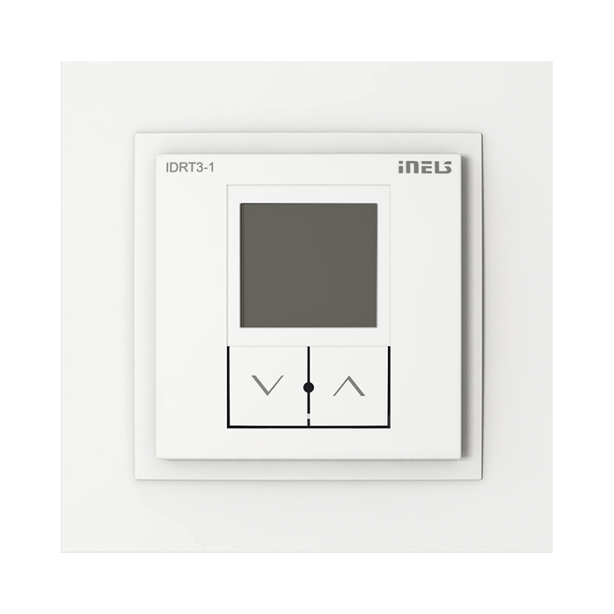
IDRT3-1 is a digital wall temperature controller used to regulate the temperature in a room.
**Temperature Correction Range**: This parameter specifies the range within which the given heating/cooling circuit can be corrected using the IDRT3-1 controller. The correction range can be set within ±3, ±4, or ±5 °C, (optional in SW iDM3).
**Integrated Heat Sensor**: The temperature controller is equipped with an integrated heat sensor for measuring the room temperature.
**Analog Digital Inputs (AIN/DIN)**: The controller features two analog/digital inputs that can be used to connect potential-free contacts or an external temperature sensor (TC/TZ) (e.g. for measuring the floor temperature).
**Display**: The controller's display shows the current temperature, and pressing one of the two buttons under the display allows users to control the desired temperature.
**Backlight**: The display's readability improves after pressing the button to activate the backlight, enhancing visibility in various lighting conditions.
**Thermo-regulator assignment**: The heating/cooling circuit is assigned to a Thermo-regulator using the iDM3 software.
**Temperature Correction Duration**: When temperature correction is applied within the specified range, the change remains valid until the next time mark within the established schedule in the iDM3 software. This ensures consistent temperature control based on predefined schedules.
**Mounting Design**: The IDRT3-1 in LOGUS90 design is intended for mounting into an installation box, providing a streamlined and integrated installation solution.
## Exemplary circuit diagram/ Wiring Diagram

## Compatibility chart ( CU, minimal FW version and Integration)
{% hint style="info" %}
*The chart illustrates the compatibility between digital room thermo-regulator and various central units, firmware versions, and integration options.*
{% endhint %}
| SL No | Support Central units | Support FW | Support in MQTT | Support in HASS |
| ----- | --------------------- | ----------- | --------------- | --------------- |
| 1 | CU3-01M | 02.46.00 | NA | NA |
| 2 | CU3-02M | 02.46.00 | NA | NA |
| 3 | CU3-07M | 04.02.00 | Yes | Yes |
| 4 | CU3-08M | 04.02.00 | Yes | Yes |
| 6 | CU3-09M | Preparation | Preparation | Preparation |
| 7 | CU3-10M | Preparation | Preparation | Preparation |
## Programming in iDM
**Introduction**
iNELS Design Manager, or IDM3, is for programming iNELS units. This software serves as the platform for configuring device parameters, defining functions, and executing the programming required for iNELS units.
Device parameters, such as sensor range and thresholds, backlights, and operational modes, can be easily adjusted within the IDM3.
The process of programming in IDM3 typically involves defining functions and establishing logical connections between different devices. This allows for the creation of automation scenarios and the implementation of intelligent control strategies.
**Starting up**
Select the "***blue control icon"*** as shown in ***Fig 1*** > Clicking on the option ***"New project from default template“*** allows you to create a new project from a predefined template.
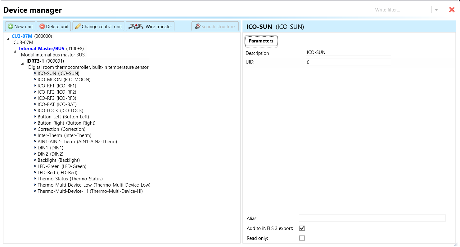
Select the "***Device manager"*** (***Fig 1***)> Add "***New unit*** "> Select the central unit > Add "***New*** ***unit"***>Select the "***Internal-Master/ BUS">*** Add "***New unit*** "> Add the devices> Click on the devices to see the "***Parameters"***.

**Parameters: Parameters** in the iNELS devices refer to the measurable factors or characteristics that define the behavior or performance of the device. These could include electrical properties, physical dimensions, environmental conditions, and various other specifications depending on the type of device.
These are settings specific to individual devices within your automation system. The specific parameters of the IDRT3-1 in the iDM as shown in ***Fig.2.***

Clicking on the IDRT3-1 (***Fig.2***), will navigate to the selected firmware, address, name, and description, along with other parameters as described below :
**Temperature Sensor**: The IDRT3 device is equipped with a temperature sensor used to measure the ambient temperature in the room or space where it is installed. This sensor provides the device with real-time temperature data for temperature regulation and control.
**Correction Range**: The correction range parameter specifies the range within which the temperature setting can be adjusted or corrected using the IDRT3 device. The correction range typically allows users to fine-tune the desired temperature within a certain range to meet their comfort or operational requirements. The correction range can be configured within ±3, ±4, or ±5 °C, providing flexibility in temperature adjustment.

**Temperature View**: The temperature view parameter refers to the display feature of the IDRT3 device that shows the current temperature. Users can view the current temperature reading on the device's display, allowing them to monitor the temperature in the room where the device is installed. This feature provides users with real-time temperature information for comfort and control purposes.

**ICO-SUN**: This parameter refers to an icon or indicator related to sunlight or daytime conditions. It indicates the device's status or provides information about daylight conditions.
**ICO-MOON**: Similar to ICO-SUN, ICO-MOON refers to an icon or indicator related to nighttime conditions. It indicates the device's status or provides information about nighttime conditions.
**ICO-RF1, 2, 3**: These parameters refer to icons or indicators related to RF (radio frequency) communication. They indicate the status of RF communication channels or signal strength.
**ICO-BAT**: ICO-BAT refers to an icon or indicator related to battery status. It indicate the remaining battery level or alert users when the battery is low.
**ICO-LOCK**: ICO-LOCK refers to an icon or indicator related to locking or security status. It indicate whether the device is locked or unlocked.
**Button-Left**: This parameter likely refers to a button on the left side of the device. It used for is user input or allows users to control the desired temperature.

* **Split Strictly Long/Short Press**: This parameter defines the behavior of the button regarding split strictly long/short presses. In other words, when the button is pressed for a short duration (short press) or held down for an extended period (long press), different actions or functions may be triggered.
**Button-Right**: Similar to Button-Left, Button-Right likely refers to a button on the right side of the device, used for user input or allows users to control the desired temperature.
**Correction**: Correction refers to the parameter for adjusting or correcting settings or values. In context of the device, it may allow users to fine-tune temperature settings or other parameters.
**Inter-Therm**: Inter-Therm refers to the temperature sensor integrated into the device. It is used to measure ambient temperature or provide temperature feedback for control .

* **Offset Temperature:** this parameter allows for calibration of the sensor readings by adding or substracting a constant value. It helps to compensate for inaccuracies in sensor measurements or align readings with a reference temperature.
* **Minimal Temperature:** Sets the minimum allowable temperature reading from the sensor. If the temperature measured by the sensor falls below this value, it may indicate a fault condition or trigger an alarm.
* **Maximal Temperature:** Sets the maximum allowable temperature reading from the sensor. If the temperature measured exceeds this value, it may indicate a fault condition or trigger an alarm.
* **Average Time:** - Defines the time period over which multiple temperature readings are averaged to obtain a stable and accurate measurement.
**AIN1-AIN2-Therm**: These parameters refer to analog inputs (AIN) used for temperature measurement (Therm). They may allow connection to external temperature sensors for additional temperature monitoring.


* **Sensor Type**: This parameter defines the type of temperature sensor connected to the AIN1- AIN2- Therm input. It specifies the model of the temperature sensor, such as TC/TZ for thermocouples. The sensor type parameter ensures compatibility between the connected sensor and the device, allowing accurate temperature measurement.
* **Offset Temperature:** this parameter allows for calibration of the sensor readings by adding or subtracting a constant value. It helps to compensate for inaccuracies in sensor measurements or align readings with a reference temperature.
* **Minimal Temperature:** Sets the minimum allowable temperature reading from the sensor. If the temperature measured by the sensor falls below this value, it may indicate a fault condition or trigger an alarm.
* **Maximal Temperature:** Sets the maximum allowable temperature reading from the sensor. If the temperature measured exceeds this value, it may indicate a fault condition or trigger an alarm.
* **Average Time:** - Defines the time period over which multiple temperature readings are averaged to obtain a stable and accurate measurement.
**DIN1, 2**: DIN1 and DIN2 refer to digital inputs used for various purposes such as receiving signals from external devices or sensors.

**Backlight**: Blacklight refers to the parameter controlling the Blacklight feature of the device's display. It allows users to adjust the brightness or turn the backlight on/off.
**LED-Green**: LED-Green \ refers to a green LED indicator on the device. It indicates status or condition, such as power on.
**LED-Red**: LED-Red refers to a red LED indicator on the device. It indicates the power-off status in the thermo-regulator.
**Thermo-Status**: Thermo-Status refers to the status of the device's temperature control function. It indicates whether the device is actively controlling temperature or in standby mode.
**Thermo-Multi-Device-Low**: Thermo-Multi-Device-Low refers to a low temperature setting for multi-device temperature control. It may be used in systems where multiple devices work together to maintain a specific temperature range.
**Thermo-Multi-Device-Hi**: Thermo-Multi-Device-Hi refers to a high temperature setting for multi-device temperature control, used in conjunction with Thermo-Multi-Device-Low to maintain a desired temperature range.
## Exports for iNELS Cloud and APP
#### Setting Up Control and Monitoring for iNELS Cloud and iNELS App
It is possible to control and monitor all the bus units in iNELS cloud and iNELS app. There are two stages to set up this function. Stage one is to do configuration in iDM3 and stage 2 is to do Configuration in iNELS cloud page and iNELS app.
#### Configuration in iDM3.
**1. Unit and Parameter Selection:**
Begin by accessing the iDM3 interface on your PC connected to CU. Navigate to the Device Manager section and carefully select the units and parameters you wish to control. This step is essential for determining what gets exported to the iNELS cloud and app.

**2. CU Configuration and Third-Party Settings :**
After the above step, go to the CU configuration in the iDM3, and select the page for third-party settings.
Inside the third-party settings page, designate the port for cloud connection. Set the mode of operation and choose the numerical system as hexadecimal. Pay close attention to verifying and configuring all essential parameters for successful cloud export.

**3. Cloud Settings:**
Move on to the Cloud Settings section within iDM3.
Input the details of your iNELS cloud account. If you haven't created one, utilize the "New User" tab on the iNELS Cloud web page to establish a free account. ([Inels Cloud - ElkoEP](https://inels.cloud/auth/login)).
Select the mode and input the cloud account credentials. Save the project to the central unit to generate and store the export project file in the iNELS cloud account.

#### Configuration in iNELS cloud page and iNELS App.
**1. Online Status Verification:**
Once the cloud credentials and export settings in iDM3 are configured successfully, check the iNELS cloud account's Gateway section. Confirm that the Central Unit (CU) is online and that the export file has been automatically sent to the cloud under your account.

**2. Device Creation in Cloud Platform:**
In the cloud platform, you have to create new devices in order to control it remotely.
In the device tab, you will find the add device button, which can be used to associate export elements from IDM with the required types and icons.

After entering any name of the device, you select the icon, the MAC address of the communication gateway (in this case CU3), a specific type of device and the address of a specific function and element from the iNELS BUS system.
Note: In order to be able to use the iNELS application for communication with CU3 over the local network or the cloud, it is necessary to create a configuration on the website.
Follow these steps meticulously to ensure a seamless configuration process for controlling and monitoring all bus units through iNELS cloud and iNELS app.
## 3rd Party Integration with iNELS BUS
#### 3rd Party Integration (MQTT)
* iNELS units support MQTT integration on central units CU3-07M, CU3-08M, CU3-09M, and CU3-10M. It is necessary to select the devices and parameters for 3rd party integration on the device manager in the iDM.
* Please note that you have an MQTT broker (local or cloud) running in the installation for this integration.
* After you have a working MQTT broker you need to configure iNELS Central units to communicate with it. If you have no knowledge of what MQTT is, you can learn about it from MQTT Essentials articles.
* There is a pre-installed MQTT broker in the iNLES bridge, it can be used to connect the iNELS Central units for integration in your projects.
**Configuration in iDM3: Select units of 3rd Party integration.**
1. **Unit and Parameter Selection:**
Begin by accessing the iDM3 interface on your PC connected to CU. Navigate to the Device Manager section and carefully select the units and parameters you wish to control. This step is essential for determining what gets exported to the 3rd party integration via MQTT.
2\. **CU Configuration and Third-Party Settings :**
After the above step, go to the CU configuration in the iDM3, and select the page for third party settings.
Inside the third-party settings page, designate the port for third-party connection. Set the mode of operation and choose the numerical system as hexadecimal. Pay close attention to verifying and configuring all essential parameters for successful third-party integration.

3\. **MQTT Settings:**
Move on to the MQTT Settings section within iDM3.
Input the details of your MQTT broker.
Select the mode and input the broker credentials such as IP, port username and password. Save the project to the central unit.

#### MQTT payload
{% embed url="" %}
## Appendices
{% hint style="info" %}
*Provide any optional, supplementary information that may help in providing a more comprehensive understanding of the product feature*
{% endhint %}
{% embed url="" %}
---
# Agent Instructions
This documentation is published with GitBook. GitBook is the documentation platform designed so that both humans and AI agents can read, navigate, and reason over technical content effectively. Learn more at gitbook.com.
## Querying This Documentation
If you need additional information that is not directly available in this page, you can query the documentation dynamically by asking a question.
Perform an HTTP GET request on the current page URL with the `ask` query parameter, and the optional `goal` query parameter:
```
GET https://wiki.inels.com/inels-bus/technical-manual-products/thermo-regulators/idrt3-1.md?ask=&goal=
```
`ask` is the immediate question: it should be specific, self-contained, and written in natural language.
`goal` is optional and describes the broader end goal you are ultimately trying to accomplish on behalf of the user. GitBook uses it to tailor the answer towards what is most useful for that goal.
The response will contain a direct answer to the question and relevant excerpts and sources from the documentation.
Use this mechanism when the answer is not explicitly present in the current page, you need clarification or additional context, or you want to retrieve related documentation sections.
 ### Key Features
IDRT3-1 is a digital wall temperature controller used to regulate the temperature in a room.
**Temperature Correction Range**: This parameter specifies the range within which the given heating/cooling circuit can be corrected using the IDRT3-1 controller. The correction range can be set within ±3, ±4, or ±5 °C, (optional in SW iDM3).
**Integrated Heat Sensor**: The temperature controller is equipped with an integrated heat sensor for measuring the room temperature.
**Analog Digital Inputs (AIN/DIN)**: The controller features two analog/digital inputs that can be used to connect potential-free contacts or an external temperature sensor (TC/TZ) (e.g. for measuring the floor temperature).
**Display**: The controller's display shows the current temperature, and pressing one of the two buttons under the display allows users to control the desired temperature.
**Backlight**: The display's readability improves after pressing the button to activate the backlight, enhancing visibility in various lighting conditions.
**Thermo-regulator assignment**: The heating/cooling circuit is assigned to a Thermo-regulator using the iDM3 software.
**Temperature Correction Duration**: When temperature correction is applied within the specified range, the change remains valid until the next time mark within the established schedule in the iDM3 software. This ensures consistent temperature control based on predefined schedules.
**Mounting Design**: The IDRT3-1 in LOGUS90 design is intended for mounting into an installation box, providing a streamlined and integrated installation solution.
## Exemplary circuit diagram/ Wiring Diagram

## Compatibility chart ( CU, minimal FW version and Integration)
{% hint style="info" %}
*The chart illustrates the compatibility between digital room thermo-regulator and various central units, firmware versions, and integration options.*
{% endhint %}
| SL No | Support Central units | Support FW | Support in MQTT | Support in HASS |
| ----- | --------------------- | ----------- | --------------- | --------------- |
| 1 | CU3-01M | 02.46.00 | NA | NA |
| 2 | CU3-02M | 02.46.00 | NA | NA |
| 3 | CU3-07M | 04.02.00 | Yes | Yes |
| 4 | CU3-08M | 04.02.00 | Yes | Yes |
| 6 | CU3-09M | Preparation | Preparation | Preparation |
| 7 | CU3-10M | Preparation | Preparation | Preparation |
## Programming in iDM
**Introduction**
iNELS Design Manager, or IDM3, is for programming iNELS units. This software serves as the platform for configuring device parameters, defining functions, and executing the programming required for iNELS units.
Device parameters, such as sensor range and thresholds, backlights, and operational modes, can be easily adjusted within the IDM3.
The process of programming in IDM3 typically involves defining functions and establishing logical connections between different devices. This allows for the creation of automation scenarios and the implementation of intelligent control strategies.
**Starting up**
Select the "***blue control icon"*** as shown in ***Fig 1*** > Clicking on the option ***"New project from default template“*** allows you to create a new project from a predefined template.
Select the "***Device manager"*** (***Fig 1***)> Add "***New unit*** "> Select the central unit > Add "***New*** ***unit"***>Select the "***Internal-Master/ BUS">*** Add "***New unit*** "> Add the devices> Click on the devices to see the "***Parameters"***.

**Parameters: Parameters** in the iNELS devices refer to the measurable factors or characteristics that define the behavior or performance of the device. These could include electrical properties, physical dimensions, environmental conditions, and various other specifications depending on the type of device.
These are settings specific to individual devices within your automation system. The specific parameters of the IDRT3-1 in the iDM as shown in ***Fig.2.***

Clicking on the IDRT3-1 (***Fig.2***), will navigate to the selected firmware, address, name, and description, along with other parameters as described below :
**Temperature Sensor**: The IDRT3 device is equipped with a temperature sensor used to measure the ambient temperature in the room or space where it is installed. This sensor provides the device with real-time temperature data for temperature regulation and control.
**Correction Range**: The correction range parameter specifies the range within which the temperature setting can be adjusted or corrected using the IDRT3 device. The correction range typically allows users to fine-tune the desired temperature within a certain range to meet their comfort or operational requirements. The correction range can be configured within ±3, ±4, or ±5 °C, providing flexibility in temperature adjustment.

**Temperature View**: The temperature view parameter refers to the display feature of the IDRT3 device that shows the current temperature. Users can view the current temperature reading on the device's display, allowing them to monitor the temperature in the room where the device is installed. This feature provides users with real-time temperature information for comfort and control purposes.

**ICO-SUN**: This parameter refers to an icon or indicator related to sunlight or daytime conditions. It indicates the device's status or provides information about daylight conditions.
**ICO-MOON**: Similar to ICO-SUN, ICO-MOON refers to an icon or indicator related to nighttime conditions. It indicates the device's status or provides information about nighttime conditions.
**ICO-RF1, 2, 3**: These parameters refer to icons or indicators related to RF (radio frequency) communication. They indicate the status of RF communication channels or signal strength.
**ICO-BAT**: ICO-BAT refers to an icon or indicator related to battery status. It indicate the remaining battery level or alert users when the battery is low.
**ICO-LOCK**: ICO-LOCK refers to an icon or indicator related to locking or security status. It indicate whether the device is locked or unlocked.
**Button-Left**: This parameter likely refers to a button on the left side of the device. It used for is user input or allows users to control the desired temperature.

* **Split Strictly Long/Short Press**: This parameter defines the behavior of the button regarding split strictly long/short presses. In other words, when the button is pressed for a short duration (short press) or held down for an extended period (long press), different actions or functions may be triggered.
**Button-Right**: Similar to Button-Left, Button-Right likely refers to a button on the right side of the device, used for user input or allows users to control the desired temperature.
**Correction**: Correction refers to the parameter for adjusting or correcting settings or values. In context of the device, it may allow users to fine-tune temperature settings or other parameters.
**Inter-Therm**: Inter-Therm refers to the temperature sensor integrated into the device. It is used to measure ambient temperature or provide temperature feedback for control .

* **Offset Temperature:** this parameter allows for calibration of the sensor readings by adding or substracting a constant value. It helps to compensate for inaccuracies in sensor measurements or align readings with a reference temperature.
* **Minimal Temperature:** Sets the minimum allowable temperature reading from the sensor. If the temperature measured by the sensor falls below this value, it may indicate a fault condition or trigger an alarm.
* **Maximal Temperature:** Sets the maximum allowable temperature reading from the sensor. If the temperature measured exceeds this value, it may indicate a fault condition or trigger an alarm.
* **Average Time:** - Defines the time period over which multiple temperature readings are averaged to obtain a stable and accurate measurement.
**AIN1-AIN2-Therm**: These parameters refer to analog inputs (AIN) used for temperature measurement (Therm). They may allow connection to external temperature sensors for additional temperature monitoring.


* **Sensor Type**: This parameter defines the type of temperature sensor connected to the AIN1- AIN2- Therm input. It specifies the model of the temperature sensor, such as TC/TZ for thermocouples. The sensor type parameter ensures compatibility between the connected sensor and the device, allowing accurate temperature measurement.
* **Offset Temperature:** this parameter allows for calibration of the sensor readings by adding or subtracting a constant value. It helps to compensate for inaccuracies in sensor measurements or align readings with a reference temperature.
* **Minimal Temperature:** Sets the minimum allowable temperature reading from the sensor. If the temperature measured by the sensor falls below this value, it may indicate a fault condition or trigger an alarm.
* **Maximal Temperature:** Sets the maximum allowable temperature reading from the sensor. If the temperature measured exceeds this value, it may indicate a fault condition or trigger an alarm.
* **Average Time:** - Defines the time period over which multiple temperature readings are averaged to obtain a stable and accurate measurement.
**DIN1, 2**: DIN1 and DIN2 refer to digital inputs used for various purposes such as receiving signals from external devices or sensors.

**Backlight**: Blacklight refers to the parameter controlling the Blacklight feature of the device's display. It allows users to adjust the brightness or turn the backlight on/off.
**LED-Green**: LED-Green \ refers to a green LED indicator on the device. It indicates status or condition, such as power on.
**LED-Red**: LED-Red refers to a red LED indicator on the device. It indicates the power-off status in the thermo-regulator.
**Thermo-Status**: Thermo-Status refers to the status of the device's temperature control function. It indicates whether the device is actively controlling temperature or in standby mode.
**Thermo-Multi-Device-Low**: Thermo-Multi-Device-Low refers to a low temperature setting for multi-device temperature control. It may be used in systems where multiple devices work together to maintain a specific temperature range.
**Thermo-Multi-Device-Hi**: Thermo-Multi-Device-Hi refers to a high temperature setting for multi-device temperature control, used in conjunction with Thermo-Multi-Device-Low to maintain a desired temperature range.
## Exports for iNELS Cloud and APP
#### Setting Up Control and Monitoring for iNELS Cloud and iNELS App
It is possible to control and monitor all the bus units in iNELS cloud and iNELS app. There are two stages to set up this function. Stage one is to do configuration in iDM3 and stage 2 is to do Configuration in iNELS cloud page and iNELS app.
#### Configuration in iDM3.
**1. Unit and Parameter Selection:**
Begin by accessing the iDM3 interface on your PC connected to CU. Navigate to the Device Manager section and carefully select the units and parameters you wish to control. This step is essential for determining what gets exported to the iNELS cloud and app.

**2. CU Configuration and Third-Party Settings :**
After the above step, go to the CU configuration in the iDM3, and select the page for third-party settings.
Inside the third-party settings page, designate the port for cloud connection. Set the mode of operation and choose the numerical system as hexadecimal. Pay close attention to verifying and configuring all essential parameters for successful cloud export.

**3. Cloud Settings:**
Move on to the Cloud Settings section within iDM3.
Input the details of your iNELS cloud account. If you haven't created one, utilize the "New User" tab on the iNELS Cloud web page to establish a free account. ([Inels Cloud - ElkoEP](https://inels.cloud/auth/login)).
Select the mode and input the cloud account credentials. Save the project to the central unit to generate and store the export project file in the iNELS cloud account.

#### Configuration in iNELS cloud page and iNELS App.
**1. Online Status Verification:**
Once the cloud credentials and export settings in iDM3 are configured successfully, check the iNELS cloud account's Gateway section. Confirm that the Central Unit (CU) is online and that the export file has been automatically sent to the cloud under your account.

**2. Device Creation in Cloud Platform:**
In the cloud platform, you have to create new devices in order to control it remotely.
In the device tab, you will find the add device button, which can be used to associate export elements from IDM with the required types and icons.

After entering any name of the device, you select the icon, the MAC address of the communication gateway (in this case CU3), a specific type of device and the address of a specific function and element from the iNELS BUS system.
Note: In order to be able to use the iNELS application for communication with CU3 over the local network or the cloud, it is necessary to create a configuration on the website.
Follow these steps meticulously to ensure a seamless configuration process for controlling and monitoring all bus units through iNELS cloud and iNELS app.
## 3rd Party Integration with iNELS BUS
#### 3rd Party Integration (MQTT)
* iNELS units support MQTT integration on central units CU3-07M, CU3-08M, CU3-09M, and CU3-10M. It is necessary to select the devices and parameters for 3rd party integration on the device manager in the iDM.
* Please note that you have an MQTT broker (local or cloud) running in the installation for this integration.
* After you have a working MQTT broker you need to configure iNELS Central units to communicate with it. If you have no knowledge of what MQTT is, you can learn about it from MQTT Essentials articles.
### Key Features
IDRT3-1 is a digital wall temperature controller used to regulate the temperature in a room.
**Temperature Correction Range**: This parameter specifies the range within which the given heating/cooling circuit can be corrected using the IDRT3-1 controller. The correction range can be set within ±3, ±4, or ±5 °C, (optional in SW iDM3).
**Integrated Heat Sensor**: The temperature controller is equipped with an integrated heat sensor for measuring the room temperature.
**Analog Digital Inputs (AIN/DIN)**: The controller features two analog/digital inputs that can be used to connect potential-free contacts or an external temperature sensor (TC/TZ) (e.g. for measuring the floor temperature).
**Display**: The controller's display shows the current temperature, and pressing one of the two buttons under the display allows users to control the desired temperature.
**Backlight**: The display's readability improves after pressing the button to activate the backlight, enhancing visibility in various lighting conditions.
**Thermo-regulator assignment**: The heating/cooling circuit is assigned to a Thermo-regulator using the iDM3 software.
**Temperature Correction Duration**: When temperature correction is applied within the specified range, the change remains valid until the next time mark within the established schedule in the iDM3 software. This ensures consistent temperature control based on predefined schedules.
**Mounting Design**: The IDRT3-1 in LOGUS90 design is intended for mounting into an installation box, providing a streamlined and integrated installation solution.
## Exemplary circuit diagram/ Wiring Diagram

## Compatibility chart ( CU, minimal FW version and Integration)
{% hint style="info" %}
*The chart illustrates the compatibility between digital room thermo-regulator and various central units, firmware versions, and integration options.*
{% endhint %}
| SL No | Support Central units | Support FW | Support in MQTT | Support in HASS |
| ----- | --------------------- | ----------- | --------------- | --------------- |
| 1 | CU3-01M | 02.46.00 | NA | NA |
| 2 | CU3-02M | 02.46.00 | NA | NA |
| 3 | CU3-07M | 04.02.00 | Yes | Yes |
| 4 | CU3-08M | 04.02.00 | Yes | Yes |
| 6 | CU3-09M | Preparation | Preparation | Preparation |
| 7 | CU3-10M | Preparation | Preparation | Preparation |
## Programming in iDM
**Introduction**
iNELS Design Manager, or IDM3, is for programming iNELS units. This software serves as the platform for configuring device parameters, defining functions, and executing the programming required for iNELS units.
Device parameters, such as sensor range and thresholds, backlights, and operational modes, can be easily adjusted within the IDM3.
The process of programming in IDM3 typically involves defining functions and establishing logical connections between different devices. This allows for the creation of automation scenarios and the implementation of intelligent control strategies.
**Starting up**
Select the "***blue control icon"*** as shown in ***Fig 1*** > Clicking on the option ***"New project from default template“*** allows you to create a new project from a predefined template.
Select the "***Device manager"*** (***Fig 1***)> Add "***New unit*** "> Select the central unit > Add "***New*** ***unit"***>Select the "***Internal-Master/ BUS">*** Add "***New unit*** "> Add the devices> Click on the devices to see the "***Parameters"***.

**Parameters: Parameters** in the iNELS devices refer to the measurable factors or characteristics that define the behavior or performance of the device. These could include electrical properties, physical dimensions, environmental conditions, and various other specifications depending on the type of device.
These are settings specific to individual devices within your automation system. The specific parameters of the IDRT3-1 in the iDM as shown in ***Fig.2.***

Clicking on the IDRT3-1 (***Fig.2***), will navigate to the selected firmware, address, name, and description, along with other parameters as described below :
**Temperature Sensor**: The IDRT3 device is equipped with a temperature sensor used to measure the ambient temperature in the room or space where it is installed. This sensor provides the device with real-time temperature data for temperature regulation and control.
**Correction Range**: The correction range parameter specifies the range within which the temperature setting can be adjusted or corrected using the IDRT3 device. The correction range typically allows users to fine-tune the desired temperature within a certain range to meet their comfort or operational requirements. The correction range can be configured within ±3, ±4, or ±5 °C, providing flexibility in temperature adjustment.

**Temperature View**: The temperature view parameter refers to the display feature of the IDRT3 device that shows the current temperature. Users can view the current temperature reading on the device's display, allowing them to monitor the temperature in the room where the device is installed. This feature provides users with real-time temperature information for comfort and control purposes.

**ICO-SUN**: This parameter refers to an icon or indicator related to sunlight or daytime conditions. It indicates the device's status or provides information about daylight conditions.
**ICO-MOON**: Similar to ICO-SUN, ICO-MOON refers to an icon or indicator related to nighttime conditions. It indicates the device's status or provides information about nighttime conditions.
**ICO-RF1, 2, 3**: These parameters refer to icons or indicators related to RF (radio frequency) communication. They indicate the status of RF communication channels or signal strength.
**ICO-BAT**: ICO-BAT refers to an icon or indicator related to battery status. It indicate the remaining battery level or alert users when the battery is low.
**ICO-LOCK**: ICO-LOCK refers to an icon or indicator related to locking or security status. It indicate whether the device is locked or unlocked.
**Button-Left**: This parameter likely refers to a button on the left side of the device. It used for is user input or allows users to control the desired temperature.

* **Split Strictly Long/Short Press**: This parameter defines the behavior of the button regarding split strictly long/short presses. In other words, when the button is pressed for a short duration (short press) or held down for an extended period (long press), different actions or functions may be triggered.
**Button-Right**: Similar to Button-Left, Button-Right likely refers to a button on the right side of the device, used for user input or allows users to control the desired temperature.
**Correction**: Correction refers to the parameter for adjusting or correcting settings or values. In context of the device, it may allow users to fine-tune temperature settings or other parameters.
**Inter-Therm**: Inter-Therm refers to the temperature sensor integrated into the device. It is used to measure ambient temperature or provide temperature feedback for control .

* **Offset Temperature:** this parameter allows for calibration of the sensor readings by adding or substracting a constant value. It helps to compensate for inaccuracies in sensor measurements or align readings with a reference temperature.
* **Minimal Temperature:** Sets the minimum allowable temperature reading from the sensor. If the temperature measured by the sensor falls below this value, it may indicate a fault condition or trigger an alarm.
* **Maximal Temperature:** Sets the maximum allowable temperature reading from the sensor. If the temperature measured exceeds this value, it may indicate a fault condition or trigger an alarm.
* **Average Time:** - Defines the time period over which multiple temperature readings are averaged to obtain a stable and accurate measurement.
**AIN1-AIN2-Therm**: These parameters refer to analog inputs (AIN) used for temperature measurement (Therm). They may allow connection to external temperature sensors for additional temperature monitoring.


* **Sensor Type**: This parameter defines the type of temperature sensor connected to the AIN1- AIN2- Therm input. It specifies the model of the temperature sensor, such as TC/TZ for thermocouples. The sensor type parameter ensures compatibility between the connected sensor and the device, allowing accurate temperature measurement.
* **Offset Temperature:** this parameter allows for calibration of the sensor readings by adding or subtracting a constant value. It helps to compensate for inaccuracies in sensor measurements or align readings with a reference temperature.
* **Minimal Temperature:** Sets the minimum allowable temperature reading from the sensor. If the temperature measured by the sensor falls below this value, it may indicate a fault condition or trigger an alarm.
* **Maximal Temperature:** Sets the maximum allowable temperature reading from the sensor. If the temperature measured exceeds this value, it may indicate a fault condition or trigger an alarm.
* **Average Time:** - Defines the time period over which multiple temperature readings are averaged to obtain a stable and accurate measurement.
**DIN1, 2**: DIN1 and DIN2 refer to digital inputs used for various purposes such as receiving signals from external devices or sensors.

**Backlight**: Blacklight refers to the parameter controlling the Blacklight feature of the device's display. It allows users to adjust the brightness or turn the backlight on/off.
**LED-Green**: LED-Green \ refers to a green LED indicator on the device. It indicates status or condition, such as power on.
**LED-Red**: LED-Red refers to a red LED indicator on the device. It indicates the power-off status in the thermo-regulator.
**Thermo-Status**: Thermo-Status refers to the status of the device's temperature control function. It indicates whether the device is actively controlling temperature or in standby mode.
**Thermo-Multi-Device-Low**: Thermo-Multi-Device-Low refers to a low temperature setting for multi-device temperature control. It may be used in systems where multiple devices work together to maintain a specific temperature range.
**Thermo-Multi-Device-Hi**: Thermo-Multi-Device-Hi refers to a high temperature setting for multi-device temperature control, used in conjunction with Thermo-Multi-Device-Low to maintain a desired temperature range.
## Exports for iNELS Cloud and APP
#### Setting Up Control and Monitoring for iNELS Cloud and iNELS App
It is possible to control and monitor all the bus units in iNELS cloud and iNELS app. There are two stages to set up this function. Stage one is to do configuration in iDM3 and stage 2 is to do Configuration in iNELS cloud page and iNELS app.
#### Configuration in iDM3.
**1. Unit and Parameter Selection:**
Begin by accessing the iDM3 interface on your PC connected to CU. Navigate to the Device Manager section and carefully select the units and parameters you wish to control. This step is essential for determining what gets exported to the iNELS cloud and app.

**2. CU Configuration and Third-Party Settings :**
After the above step, go to the CU configuration in the iDM3, and select the page for third-party settings.
Inside the third-party settings page, designate the port for cloud connection. Set the mode of operation and choose the numerical system as hexadecimal. Pay close attention to verifying and configuring all essential parameters for successful cloud export.

**3. Cloud Settings:**
Move on to the Cloud Settings section within iDM3.
Input the details of your iNELS cloud account. If you haven't created one, utilize the "New User" tab on the iNELS Cloud web page to establish a free account. ([Inels Cloud - ElkoEP](https://inels.cloud/auth/login)).
Select the mode and input the cloud account credentials. Save the project to the central unit to generate and store the export project file in the iNELS cloud account.

#### Configuration in iNELS cloud page and iNELS App.
**1. Online Status Verification:**
Once the cloud credentials and export settings in iDM3 are configured successfully, check the iNELS cloud account's Gateway section. Confirm that the Central Unit (CU) is online and that the export file has been automatically sent to the cloud under your account.

**2. Device Creation in Cloud Platform:**
In the cloud platform, you have to create new devices in order to control it remotely.
In the device tab, you will find the add device button, which can be used to associate export elements from IDM with the required types and icons.

After entering any name of the device, you select the icon, the MAC address of the communication gateway (in this case CU3), a specific type of device and the address of a specific function and element from the iNELS BUS system.
Note: In order to be able to use the iNELS application for communication with CU3 over the local network or the cloud, it is necessary to create a configuration on the website.
Follow these steps meticulously to ensure a seamless configuration process for controlling and monitoring all bus units through iNELS cloud and iNELS app.
## 3rd Party Integration with iNELS BUS
#### 3rd Party Integration (MQTT)
* iNELS units support MQTT integration on central units CU3-07M, CU3-08M, CU3-09M, and CU3-10M. It is necessary to select the devices and parameters for 3rd party integration on the device manager in the iDM.
* Please note that you have an MQTT broker (local or cloud) running in the installation for this integration.
* After you have a working MQTT broker you need to configure iNELS Central units to communicate with it. If you have no knowledge of what MQTT is, you can learn about it from MQTT Essentials articles.