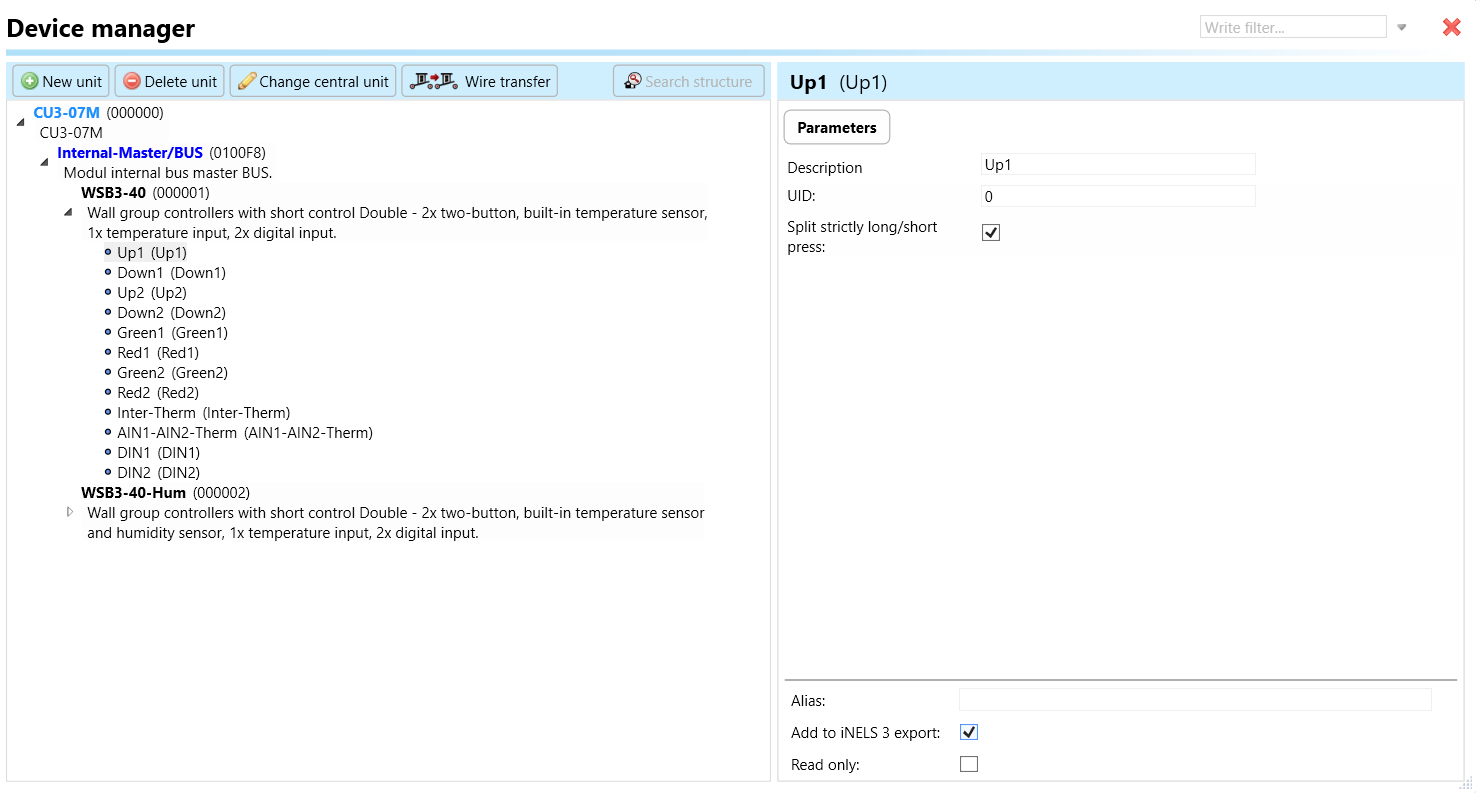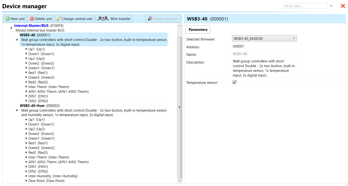
Fig.2: Parameters of WSB3-40, WSB3-40H
 ### Key Features
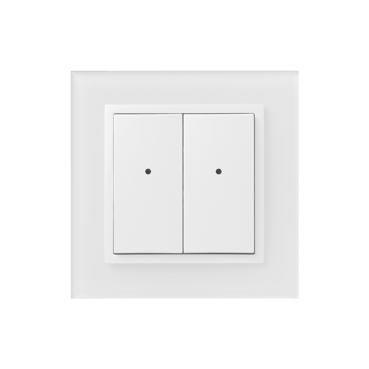
**Upstroke Control:** The WSB3-40 and WSB3-40H controllers feature upstroke control, offering elegant and pleasant control with a built-in micro-switch with low upstroke.
**Number of Channels:** Both controllers are supplied with 4 channels, providing control over multiple appliances or functions.
**Indication LEDs:** Two-colored indication LEDs are located in each controller to signal the status of controlled appliances or the status of any sensor or actuator in the system.
**Compatibility:** Wall buttons in the WSB3 series are compatible with both types of frames, LOGUS90 (85.6x85.6 or 94x94 mm), allowing for combination with double and triple frames and classic products of the series.
**Integrated Sensors and Inputs:** Each controller is equipped with a temperature sensor and two analog/digital inputs (AIN/DIN), allowing connection to two potential less contacts or one external temperature sensor TC/TZ for various applications such as floor temperature measurement.
**Flexibility and Multifunctionality:** Compared to standard wall buttons, the WSB3-40 and WSB3-40H are more flexible and multifunctional. They support functions such as controlling appliances by short and long pushes of the button, dimming, shutter control, and scenes.
**Time controlled features:** Each button can control any appliance in the system and can use a variety of centralized or time-controlled features. Accordingly, the customer can choose the simplicity/complexity of the operation. The big advantage is the possibility to change the method of control by only making software modifications without physical interventions into the structure of the building
**Customizable Functional Modes:** Each button (fold) can have different functional modes besides lighting control, including:
a) Classic wall-switch - upper button ON, bottom button OFF.
b) Button controller (impulse relay) - first press ON, second press OFF.
c) Dimmer - short press for ON/OFF
d) Time switch- ON after press, automatically OFF after set time.
e) Setting light scenes- e.g., for watching TV:
* shutters down
* main light 30% intensity
* wall-lamps 50% intensity
**Mounting:** The WSB3 controllers in LOGUS90 design are designed for mounting into an installation box, ensuring easy installation and integration into building structures.
## Exemplary circuit diagram/ Wiring Diagram

## Compatibility chart ( CU, minimal FW version and Integration)
{% hint style="info" %}
*The chart illustrates the compatibility between wall switch button and various central units, firmware versions, and integration options.*
{% endhint %}
| SL No | Support Central units | Support FW | Support in MQTT | Support in HASS |
| ----- | --------------------- | ----------- | --------------- | --------------- |
| 1 | CU3-01M | 02.83.00 | NA | NA |
| 2 | CU3-02M | 02.83.00 | NA | NA |
| 3 | CU3-07M | 04.00.00 | Yes | Yes |
| 4 | CU3-08M | 04.00.00 | Yes | Yes |
| 6 | CU3-09M | Preparation | Preparation | Preparation |
| 7 | CU3-10M | Preparation | Preparation | Preparation |
## Programming in iDM
**Introduction**
iNELS Design Manager, or IDM3, is for programming iNELS units. This software serves as the platform for configuring device parameters, defining functions, and executing the programming required for iNELS units.
Device parameters, such as sensor range and thresholds, backlights, and operational modes, can be easily adjusted within the IDM3.
The process of programming in IDM3 typically involves defining functions and establishing logical connections between different devices. This allows for the creation of automation scenarios and the implementation of intelligent control strategies.
**Starting up**
Select the "***blue control icon"*** as shown in ***Fig 1*** > Clicking on the option ***"New project from default template“*** allows you to create a new project from a predefined template.
Select the "***Device manager"*** (***Fig 1***)> Add "***New unit*** "> Select the central unit > Add "***New*** ***unit"***>Select the "***Internal-Master/ BUS">*** Add "***New unit*** "> Add the devices> Click on the devices to see the "***Parameters"***.

**Parameters:**
**Parameters** in the iNELS devices refer to the measurable factors or characteristics that define the behavior or performance of the device. These could include electrical properties, physical dimensions, environmental conditions, and various other specifications depending on the type of device.
These are settings specific to individual devices within your automation system.The specific parameters of the WSB3-40, WSB3-40H in the iDM as shown in ***Fig.2***
### Key Features
**Upstroke Control:** The WSB3-40 and WSB3-40H controllers feature upstroke control, offering elegant and pleasant control with a built-in micro-switch with low upstroke.
**Number of Channels:** Both controllers are supplied with 4 channels, providing control over multiple appliances or functions.
**Indication LEDs:** Two-colored indication LEDs are located in each controller to signal the status of controlled appliances or the status of any sensor or actuator in the system.
**Compatibility:** Wall buttons in the WSB3 series are compatible with both types of frames, LOGUS90 (85.6x85.6 or 94x94 mm), allowing for combination with double and triple frames and classic products of the series.
**Integrated Sensors and Inputs:** Each controller is equipped with a temperature sensor and two analog/digital inputs (AIN/DIN), allowing connection to two potential less contacts or one external temperature sensor TC/TZ for various applications such as floor temperature measurement.
**Flexibility and Multifunctionality:** Compared to standard wall buttons, the WSB3-40 and WSB3-40H are more flexible and multifunctional. They support functions such as controlling appliances by short and long pushes of the button, dimming, shutter control, and scenes.
**Time controlled features:** Each button can control any appliance in the system and can use a variety of centralized or time-controlled features. Accordingly, the customer can choose the simplicity/complexity of the operation. The big advantage is the possibility to change the method of control by only making software modifications without physical interventions into the structure of the building
**Customizable Functional Modes:** Each button (fold) can have different functional modes besides lighting control, including:
a) Classic wall-switch - upper button ON, bottom button OFF.
b) Button controller (impulse relay) - first press ON, second press OFF.
c) Dimmer - short press for ON/OFF
d) Time switch- ON after press, automatically OFF after set time.
e) Setting light scenes- e.g., for watching TV:
* shutters down
* main light 30% intensity
* wall-lamps 50% intensity
**Mounting:** The WSB3 controllers in LOGUS90 design are designed for mounting into an installation box, ensuring easy installation and integration into building structures.
## Exemplary circuit diagram/ Wiring Diagram

## Compatibility chart ( CU, minimal FW version and Integration)
{% hint style="info" %}
*The chart illustrates the compatibility between wall switch button and various central units, firmware versions, and integration options.*
{% endhint %}
| SL No | Support Central units | Support FW | Support in MQTT | Support in HASS |
| ----- | --------------------- | ----------- | --------------- | --------------- |
| 1 | CU3-01M | 02.83.00 | NA | NA |
| 2 | CU3-02M | 02.83.00 | NA | NA |
| 3 | CU3-07M | 04.00.00 | Yes | Yes |
| 4 | CU3-08M | 04.00.00 | Yes | Yes |
| 6 | CU3-09M | Preparation | Preparation | Preparation |
| 7 | CU3-10M | Preparation | Preparation | Preparation |
## Programming in iDM
**Introduction**
iNELS Design Manager, or IDM3, is for programming iNELS units. This software serves as the platform for configuring device parameters, defining functions, and executing the programming required for iNELS units.
Device parameters, such as sensor range and thresholds, backlights, and operational modes, can be easily adjusted within the IDM3.
The process of programming in IDM3 typically involves defining functions and establishing logical connections between different devices. This allows for the creation of automation scenarios and the implementation of intelligent control strategies.
**Starting up**
Select the "***blue control icon"*** as shown in ***Fig 1*** > Clicking on the option ***"New project from default template“*** allows you to create a new project from a predefined template.
Select the "***Device manager"*** (***Fig 1***)> Add "***New unit*** "> Select the central unit > Add "***New*** ***unit"***>Select the "***Internal-Master/ BUS">*** Add "***New unit*** "> Add the devices> Click on the devices to see the "***Parameters"***.

**Parameters:**
**Parameters** in the iNELS devices refer to the measurable factors or characteristics that define the behavior or performance of the device. These could include electrical properties, physical dimensions, environmental conditions, and various other specifications depending on the type of device.
These are settings specific to individual devices within your automation system.The specific parameters of the WSB3-40, WSB3-40H in the iDM as shown in ***Fig.2***
Fig.2: Parameters of WSB3-40, WSB3-40H