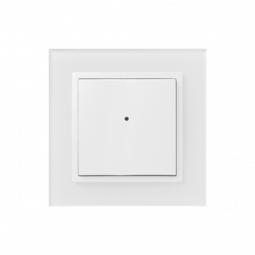
WMR3-21
Wall card reader
Overview
An overview of the product design and usage. Also contains circuit diagrams, terminal details, etc.,
Key Features
Contactless Media Reader: WMR3-21 is a wall-mounted card reader designed for reading contactless media such as smart cards and keychains. These media are commonly used for controlling access to buildings or specific parts of buildings.
Easy Control: Users can easily control the WMR3-21 using two push buttons, which can be assigned various control functions such as lighting, shading, scenes, heating, etc.
Versatile Control Applications: The WMR3-21 reader can be used to control various systems including security systems (locking/unlocking), access systems (opening doors, gates, etc.), or appliances based on assigned rights.
RFID Support: WMR3-21 supports RFID media with a carrier frequency of 13.56 MHz. It is compatible with card types such as MIFARE Ultralight, DESFire 2K (EV1), and DESFire 4K (EV1).
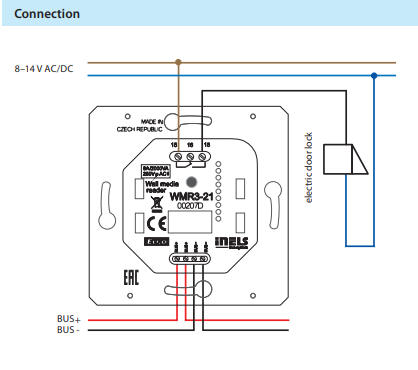
Relay Output: The device is equipped with an 8 A relay output with changeover contact AgSnO2, allowing controlled devices to be switched directly. Alternatively, any actuator in the system can be set in the software iDM3.
Indication LED: The WMR3-21 features a two-color LED in the controller cover, which can indicate not only the status of controlled appliances but also the status of any sensor or actuator in the system.
Compatibility: The wall card reader WMR3-21 is compatible with both types of frames LOGUS90 (85.6 x 85.6 or 94 x 94 mm), enabling users to combine them with double and triple frames and classic products of the series.
Exemplary circuit diagram/ Wiring Diagram
Compatibility chart ( CU, minimal FW version and Integration)
The chart illustrates the compatibility between wall card reader and various central units, firmware versions, and integration options.
1
CU3-01M
01.36.00
NA
NA
2
CU3-02M
01.36.00
NA
NA
3
CU3-07M
04.04.00.
Yes
Yes
4
CU3-08M
04.04.00.
Yes
Yes
6
CU3-09M
Preparation
Preparation
Preparation
7
CU3-10M
Preparation
Preparation
Preparation
Programming in iDM
Introduction
iNELS Design Manager, or IDM3, is for programming iNELS units. This software serves as the platform for configuring device parameters, defining functions, and executing the programming required for iNELS units.
Device parameters, such as sensor range and thresholds, backlights, and operational modes, can be easily adjusted within the IDM3.
The process of programming in IDM3 typically involves defining functions and establishing logical connections between different devices. This allows for the creation of automation scenarios and the implementation of intelligent control strategies.
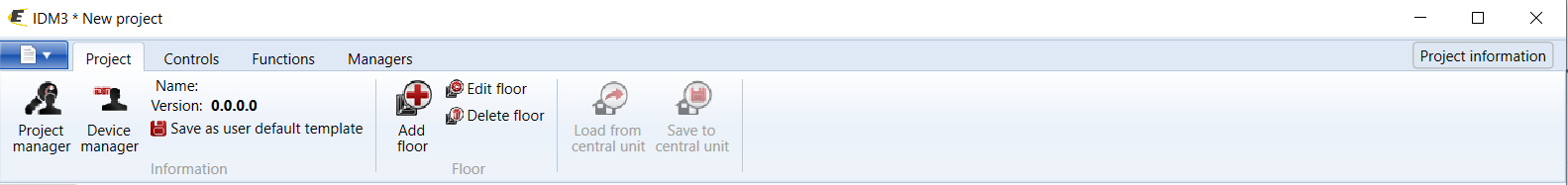
Starting up
Select the "blue control icon" as shown in Fig 1 > Clicking on the option "New project from default template“ allows you to create a new project from a predefined template.
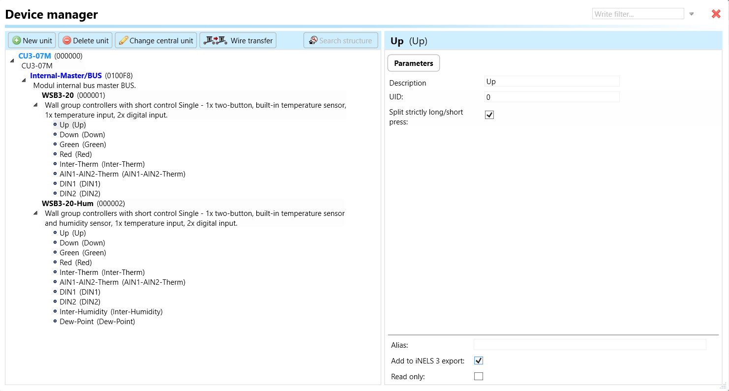
Select the "Device manager" (Fig 1)> Add "New unit "> Select the central unit > Add "New unit">Select the "Internal-Master/ BUS"> Add "New unit "> Add the devices> Click on the devices to see the "Parameters".
Parameters:
Parameters in the iNELS devices refer to the measurable factors or characteristics that define the behavior or performance of the device. These could include electrical properties, physical dimensions, environmental conditions, and various other specifications depending on the type of device.
These are settings specific to individual devices within your automation system.The specific parameters of the WMR3-21 in the iDM as shown in Fig.2
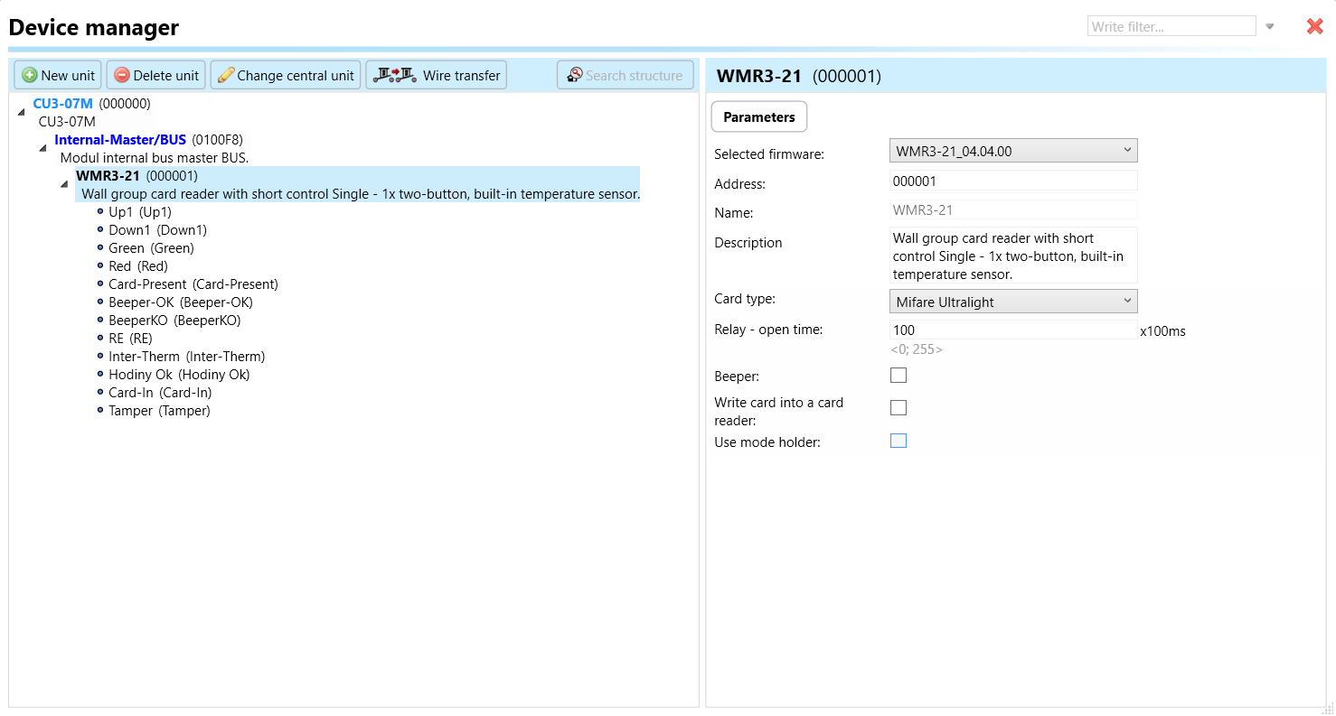
Clicking on the WMR3-21 (Fig.2), will navigate to the selected firmware, address, name, and description, along with other parameters as described below:
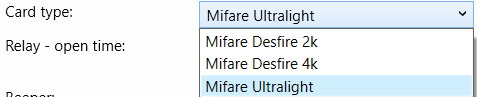
Card Type: This parameter refers to the type of contactless media supported by the WMR3-21 card reader. The card types include MIFARE Ultralight, DESFire 2K (EV1), and DESFire 4K (EV1). The card type parameter specifies the compatible formats that can be read by the card reader.
Relay- open time: The relay open-time parameter specifies the duration for which the relay output remains open after activation. This duration determines how long the controlled devices remain switched on or unlocked after a successful card read or activation event.
Beeper: The beeper parameter refers to the audible alert mechanism integrated into the WMR3-21 card reader. This feature produces sound signals to provide feedback to users, such as indicating successful card reads, error conditions, or system status changes.
White Card into a Card Reader: This parameter refers to the action of inserting a white card (a blank or unprogrammed card) into the card reader. The behavior or response of the card reader when a white card is inserted may vary based on system configuration or application-specific settings.
Use Mode Holder: This parameter is the reference usage mode or feature related to the physical holder of the card reader. It may denote a specific mode of operation or functionality associated with the physical mounting or installation of the WMR3-21 card reader, although the exact details of this parameter are not explicitly provided in the given information.
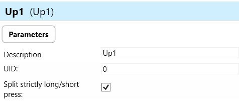
Up 1: "Up 1"refers to a function associated with the upstroke movement of the controller's buttons. This parameter defines the behavior or action initiated when the button is pressed upward.
Down 1: "Down 1" refers to a function associated with the downstroke movement of the controller's buttons. This parameter defines the behavior or action initiated when the button is released or pressed downward after being pressed.
Green LED (Light-Emitting Diode): The green LED parameter specifies the behavior associated with the green LED located on the WMR3-21 card reader. This LED may indicate status conditions such as successful card reads.
Red LED (Light-Emitting Diode): Similar to the green LED parameter, the red LED parameter specifies the behavior associated with the red LED located on the WMR3-21 card reader. This LED indicates access denials.
Card-Present: The card-present parameter indicates the detection of a contactless card or media within the proximity of the card reader. This parameter may trigger specific actions or events upon the detection of a card, such as initiating a card read process or activating access control functions.
BeeperKO: "BeeperKO" refers to a specific sound signal or alert produced by the card reader when an error or failure condition occurs (KO stands for "knockout" or failure). This parameter defines the behavior or sound associated with error states or malfunctions detected by the card reader.
RE (Relay Output): The RE parameter refers to the relay output of the WMR3-21 card reader. This parameter may specify the behavior of the relay output, which is used for controlling external devices such as door locks or access control systems.
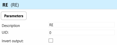
Invert output-"Invert output" refers to the ability to change the state of the output signal. When the output is inverted, a command that would normally turn the output on would instead turn it off, and vice versa.
Inter-Therm (Internal Thermometer): The inter-therm parameter refers to the internal thermometer or temperature sensor integrated into the WMR3-21 card reader. This sensor is used to monitor environmental conditions or detect temperature-related events.
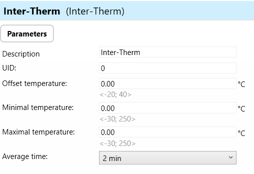
Offset Temperature: The offset temperature allows you to calibrate the sensor readings by adding or subtracting a constant value. This is useful for compensating for inaccuracies in sensor measurements or for aligning readings with a reference temperature.
Minimal Temperature: This parameter sets the minimum allowable temperature reading from the sensor. If the temperature measured by the sensor falls below this value, it may indicate a fault condition or trigger an alarm.
Maximal Temperature: Similarly, the maximal temperature parameter sets the maximum allowable temperature reading from the sensor. If the temperature measured exceeds this value, it may indicate a fault condition or trigger an alarm.
Average Time : - Defines the time period over which multiple temperature readings are averaged to obtain a stable and accurate measurement.
Hodiny Ok (Clock OK): "Hodiny Ok" refers to the status or functionality of the internal clock system within the WMR3-21 card reader. This parameter may indicate whether the internal clock is functioning correctly and providing accurate time information.
Card-In: The "Card-In" parameter indicates the detection of a card being inserted into the card reader. This parameter may trigger specific actions or events upon the insertion of a card, such as initiating a card read process or activating access control functions.
Tamper: The "Tamper" parameter indicates the detection of tampering or unauthorized access attempts on the WMR3-21 card reader. This parameter may trigger alarms or security measures to prevent unauthorized access or manipulation of the device.
Exports for iNELS Cloud and APP
Setting Up Control and Monitoring for iNELS Cloud and iNELS App
It is possible to control and monitor all the bus units in iNELS cloud and iNELS app. There are two stages to set up this function. Stage one is to do configuration in iDM3 and stage 2 is to do Configuration in iNELS cloud page and iNELS app.
Configuration in iDM3.
1. Unit and Parameter Selection:
Begin by accessing the iDM3 interface on your PC connected to CU. Navigate to the Device Manager section and carefully select the units and parameters you wish to control. This step is essential for determining what gets exported to the iNELS cloud and app.

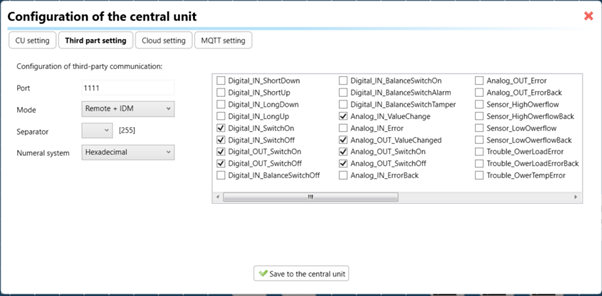
2. CU Configuration and Third-Party Settings :
After the above step, go to the CU configuration in the iDM3, and select the page for third-party settings.
Inside the third-party settings page, designate the port for cloud connection. Set the mode of operation and choose the numerical system as hexadecimal. Pay close attention to verifying and configuring all essential parameters for successful cloud export.
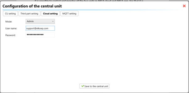
3. Cloud Settings:
Move on to the Cloud Settings section within iDM3.
Input the details of your iNELS cloud account. If you haven't created one, utilize the "New User" tab on the iNELS Cloud web page to establish a free account. (Inels Cloud - ElkoEP).
Select the mode and input the cloud account credentials. Save the project to the central unit to generate and store the export project file in the iNELS cloud account.
Configuration in iNELS cloud page and iNELS App.
1. Online Status Verification:
Once the cloud credentials and export settings in iDM3 are configured successfully, check the iNELS cloud account's Gateway section. Confirm that the Central Unit (CU) is online and that the export file has been automatically sent to the cloud under your account.
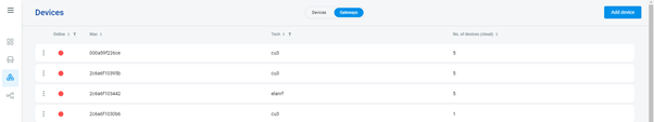
2. Device Creation in Cloud Platform:
In the cloud platform, you have to create new devices in order to control it remotely.
In the device tab, you will find the add device button, which can be used to associate export elements from IDM with the required types and icons.
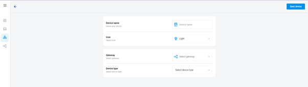
After entering any name of the device, you select the icon, the MAC address of the communication gateway (in this case CU3), a specific type of device and the address of a specific function and element from the iNELS BUS system.
Note: In order to be able to use the iNELS application for communication with CU3 over the local network or the cloud, it is necessary to create a configuration on the website.
Follow these steps meticulously to ensure a seamless configuration process for controlling and monitoring all bus units through iNELS cloud and iNELS app.
3rd Party Integration with iNELS BUS
3rd Party Integration (MQTT)
iNELS units support MQTT integration on central units CU3-07M, CU3-08M, CU3-09M, and CU3-10M. It is necessary to select the devices and parameters for 3rd party integration on the device manager in the iDM.
Please note that you have an MQTT broker (local or cloud) running in the installation for this integration.
After you have a working MQTT broker you need to configure iNELS Central units to communicate with it. If you have no knowledge of what MQTT is, you can learn about it from MQTT Essentials articles. https://www.hivemq.com/mqtt/
There is a pre-installed MQTT broker in the iNLES bridge, it can be used to connect the iNELS Central units for integration in your projects.
Configuration in iDM3: Select units of 3rd Party integration.
Unit and Parameter Selection:
Begin by accessing the iDM3 interface on your PC connected to CU. Navigate to the Device Manager section and carefully select the units and parameters you wish to control. This step is essential for determining what gets exported to the 3rd party integration via MQTT.
2. CU Configuration and Third-Party Settings :
After the above step, go to the CU configuration in the iDM3, and select the page for third party settings.
Inside the third-party settings page, designate the port for third-party connection. Set the mode of operation and choose the numerical system as hexadecimal. Pay close attention to verifying and configuring all essential parameters for successful third-party integration.
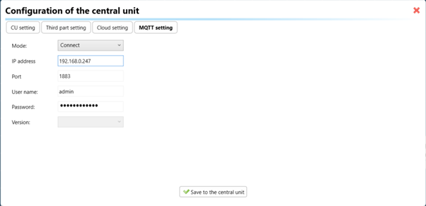
3. MQTT Settings:
Move on to the MQTT Settings section within iDM3.
Input the details of your MQTT broker.
Select the mode and input the broker credentials such as IP, port username and password. Save the project to the central unit.
MQTT payload
Appendices
Provide any optional, supplementary information that may help in providing a more comprehensive understanding of the product feature
Last updated