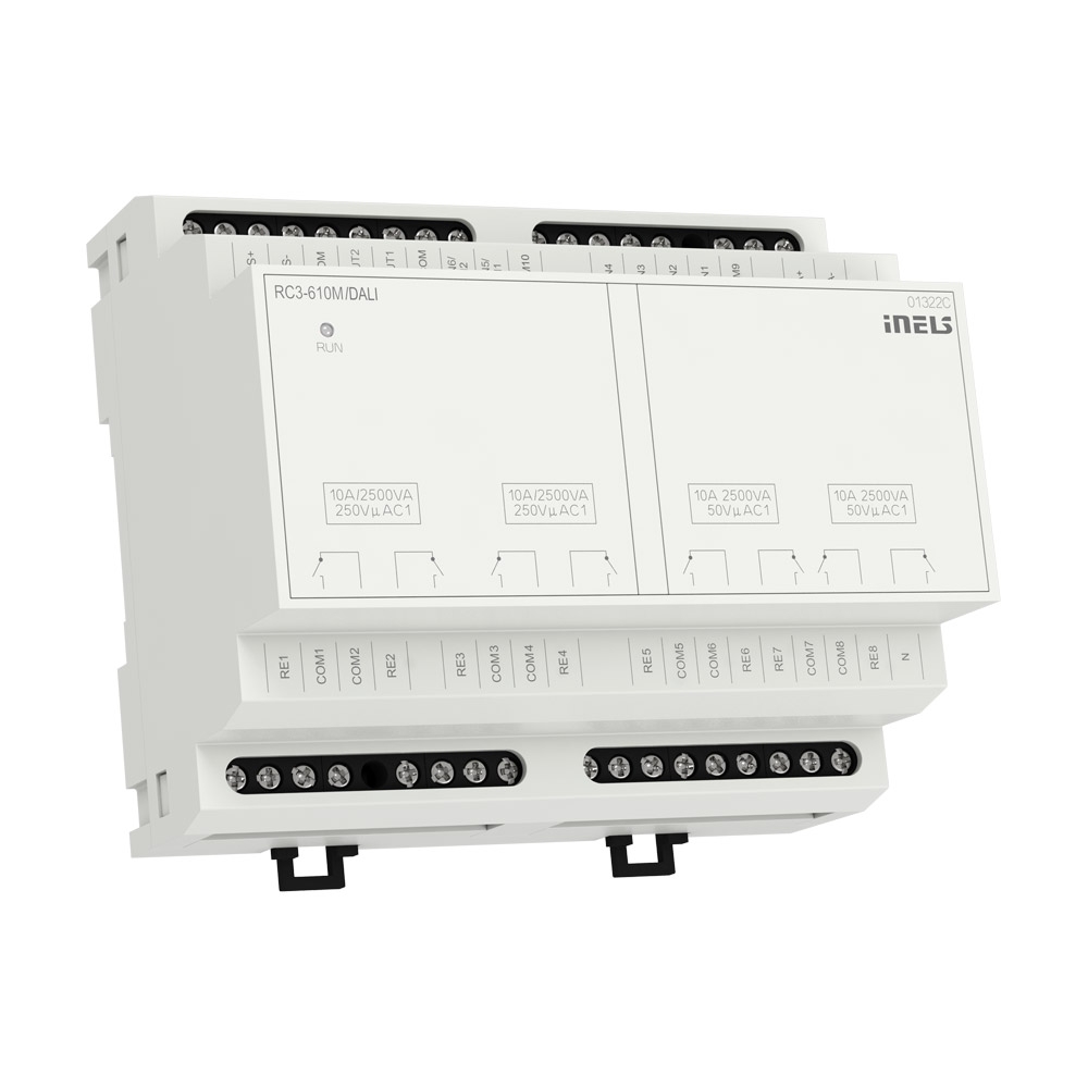
RC3-610M/DALI
Room controller with DALI dimmer
Overview of devices
Key Features
The RC3-610M/DALI is a versatile I/O actuator that provides control and monitoring capabilities for various devices, along with support for temperature sensing and DALI lighting control. The flexibility in configuration, relay outputs, and analog outputs make it suitable for applications in building automation and control systems.
Inputs: 6 binary inputs, of which 2 binary inputs can be configured as temperature inputs. Binary inputs used for connecting upto 6 devices with non-decimal contacts (e.g., switches, buttons, , EZS and EPS detectors).
Temperature Inputs: Support for TC/TZ temperature sensors. 2-wire connection for temperature sensing needs.
Relays:
8 independent relays with switching potential-free and potential contacts.
Zero crossing relays
Maximum load capacity for relay contacts: 10 A/2500 VA/AC1.
Each output contact is individually controllable.
Relays are divided into four pairs, with each pair switching on its common potential.
Analog Outputs: 2 analog outputs: 0(1)-10 V. Load capacity: Up to 10 mA. Suitable for use with thermoregulation heads, air-conditioning ventilation flaps, dimmers, or devices with analog control voltage (0-10 V or 1-10 V).
DALI System BUS: Allows control of up to 16 independent DALI addresses. Used for controlling DALI ballasts in fluorescent, LED, and other luminaires.
Configuration Software: Parameters of all configurable inputs and outputs are set using the iNELS Designer & Manager configuration software.
Mounting: 6-MODULE version designed for mounting into a switchboard. Mounting on DIN rail EN60715.
Exemplary circuit diagram/ Wiring Diagram

Compatibility chart ( CU, minimal FW version and Integration)
1
CU3-01M
01.00.00
NA
NA
2
CU3-02M
01.00.00
NA
NA
3
CU3-07M
01.00.08
Yes
Yes
4
CU3-08M
01.00.08
Yes
Yes
6
CU3-09M
Preparation
Preparation
Preparation
7
CU3-10M
Preparation
Preparation
Preparation
Programming in iDM
Introduction
iNELS Design Manager, or IDM3, is for programming iNELS units. This software serves as the platform for configuring device parameters, defining functions, and executing the programming required for iNELS units.
Device parameters, such as sensor range and thresholds, backlights, and operational modes, can be easily adjusted within the IDM3.
The process of programming in IDM3 typically involves defining functions and establishing logical connections between different devices. This allows for the creation of automation scenarios and the implementation of intelligent control strategies.
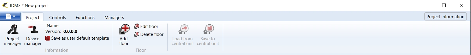
Starting up
Select the "blue control icon" as shown in Fig 1 > Clicking on the option "New project from default template“ allows you to create a new project from a predefined template.
Select the "Device manager" (Fig 1)> Add "New unit "> Select the central unit > Add "New unit"> Select the "Internal-Master/ BUS"> Add "New unit "> Add the devices> Click on the devices to see the "Parameters".
General Parameters:
Parameters in the iNELS devices refer to the measurable factors or characteristics that define the behavior or performance of the device. These could include electrical properties, physical dimensions, environmental conditions, and various other specifications depending on the type of device.
These are settings specific to individual devices within your automation system.
The specific parameters of the RC3-610M/DALI in the iDM as shown in Fig.2, Fig.3, Fig. 4.
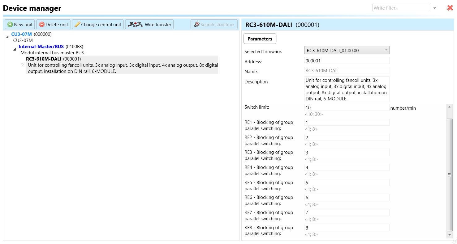
Clicking on the RC3-610M/DALI (Fig.2), will navigate to the selected firmware, unit address, name, and description, along with other parameters as described below.
It is important to add the device address for proper communication with the unit. The Hexadecimal device address can be find from the device.
Temperature sensor:
The temperature sensor input on the RC3-610M/DALI device supports the connection of TC/TZ temperature sensors.
These sensors typically utilize a 2-wire connection for temperature sensing purposes.
They are used to monitor temperature levels in the environment or specific areas.
Temperature sensors play a crucial role in applications such as HVAC systems, thermal management, and environmental monitoring.
The RC3-610M/DALI device accommodates temperature sensors to provide temperature data for control and monitoring purposes within the configured system.
Through configuration software like iNELS Designer & Manager, users can set parameters related to temperature sensors, such as calibration, temperature range, and alarm thresholds.
Switch limit:
The switch limit parameter establishes the highest allowable frequency of relay switching per minute. If the number of switch occurrences surpasses this limit within a minute, the relay will not be triggered.
RE1- RE8 Blocking group of parallel switching:

This function is responsible for preventing or halting the simultaneous switching of a relay in parallel with other relays within the designated group. For instance, if you designate RE1, RE2, and RE3 to Blocking group of parallel switching- 1, none of these relays will switch on concurrently. This feature proves useful when connecting these relays to three distinct fans in an air conditioning system. If Fan 1 is activated, Fans 2 and 3 will not switch on in parallel, effectively safeguarding the fans from simultaneous switching.
RE1- RE8- Relays are a means of remotely controlling various electrical loads, such as lights or other devices. It acts as a switch that can open or close electrical circuits, allowing or interrupting the flow of power to connected devices.

Invert output: "Invert output" refers to the ability to change the state of the output signal. When the output is inverted, a command that would normally turn the output on would instead turn it off, and vice versa.
Use default state: In the context of a switching actuator, the term "default state" pertains to the pre-established or initial condition that the actuator adopts in the absence of communication from the bus or central unit. Enabling this function ensures that the relay automatically assumes its default state, which is set to OFF.
Default Output State: Upon choosing the "use default state" option, you will be prompted to specify the default output state. This refers to the pre-established or initial condition that the actuator adopts when there is no communication from the bus stop or central unit. Upon selecting this function, the relay will transition to its default output state, which, in this case, is set to ON.
OUF-Alert-RE1-OUF Alert RE 8:
This parameter serves as an indicator for alert conditions associated with relay outputs 1 through 8 on the RC3-610M/DALI device.
The alert is activated when the switching limit surpasses the configured threshold in any of the relay outputs.
Upon activation, this alert signals users about a fault in one of the relay outputs, prompting them to investigate and take corrective measures. This is crucial to prevent potential damage to connected loads or the device itself.
The designation "RE1-8" specifies that the alert is applicable to each relay output individually, allowing users to pinpoint the specific relay output affected by the alert.
Synchro-Alert-Re1-RE 2:
This parameter serves as an indicator for alert conditions associated with the phase synchronization of relay outputs RE1 and RE2 to the Common (Com 1 and com 2).
The alert is activated when a different phase is detected connected to the common (Com1 and Com2 ) potential terminal.
Once triggered, this alert notifies users of potential phase synchronization issues between the common terminal.
Users are prompted to investigate and address the cause promptly to ensure proper wiring and prevent potential issues.
DIN 1- DIN 6:
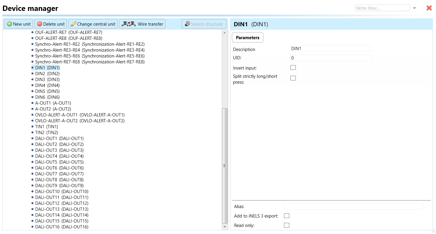
Equipped with 6 binary inputs.
2 of these inputs can be configured as temperature inputs.
Binary inputs are suitable for connecting devices with a non-decimal contact, including switches, buttons, detectors (such as EZS and EPS), and other similar devices.

Invert Input:
"Invert input" refers to a configuration setting that reverses the logic state of a digital input signal.
When "Invert input" is enabled for a specific digital input channel (DIN) on the RC3-610M device, it means that the logical interpretation of the input signal is inverted.
For instance, if a digital input channel is normally interpreted as "active" when the input signal is high (logic level 1), enabling "Invert input" would cause the channel to be interpreted as "active" when the input signal is low (logic level 0), and vice versa.
This setting is useful when the connected external device operates with an inverted logic signal, and it ensures compatibility with the RC3-610M device's input requirements.
Split Strictly Long/Short Press of DIN:
"Split strictly long/short press of DIN" is a feature that distinguishes between short and long press actions on a digital input channel (DIN).
When this feature is enabled for a specific DIN channel on the RC3-610M device, it allows the system to differentiate between short-duration button presses and long-duration button presses.
Short press actions typically trigger immediate responses or commands, while long press actions may initiate different or additional functions after a predefined duration.
Enabling "Split strictly long/short press of DIN" ensures precise detection and handling of short and long press events, enhancing the versatility and functionality of the digital input channels.
This feature is particularly useful in applications where users interact with the system using buttons or switches, providing intuitive control options for various functions or commands.
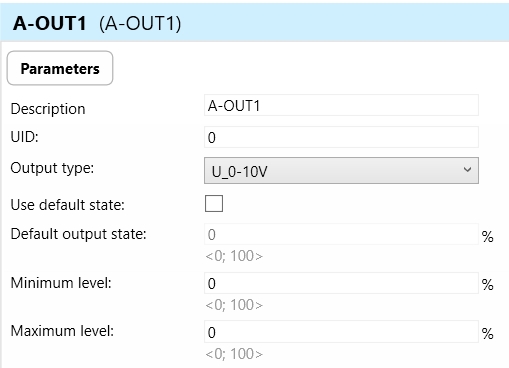
A-0UT 1 & 2:
2 analog outputs with a range of 0(1)-10 V.
Load capacity of up to 10 mA.
Analog outputs intended for use with thermoregulation heads, air-conditioning ventilation flaps, dimmers, or devices with analog control voltage (0-10 V or 1-10 V).

OVLO-ALERT-A-OUT 1- 2
"OVLO" stands for "Overvoltage Alert."
This parameter indicates an alert condition related to the analog outputs 1 and 2 on the RC3-610M device.
It is triggered when there is an overvoltage condition detected in one or both of the analog output channels.
An overvoltage alert occurs when the voltage output from the analog outputs exceeds the specified maximum rating.
Overvoltage alerts are important for preventing damage to connected devices or systems due to excessive voltage levels.
When activated, this alert notifies users of the overvoltage condition in the analog output channels, prompting them to investigate and address the underlying cause to prevent potential damage or malfunction.
TIN1
Supports the connection of TC/TZ temperature sensors.
Utilizes a 2-wire connection for temperature sensing needs.
Allows for monitoring and control based on temperature conditions.
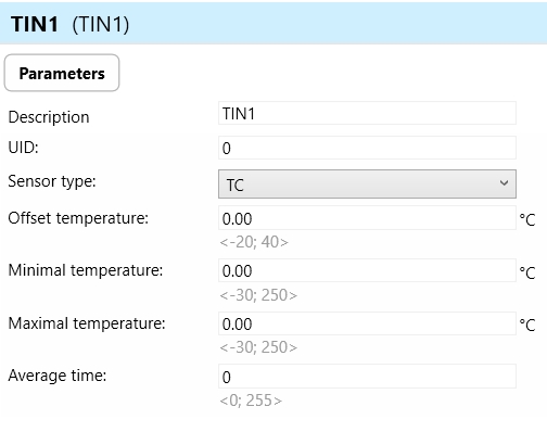
Sensor Type:
This parameter defines the type of temperature sensor connected to the TIN input.
It specifies the technology or model of the temperature sensor, such as TC/TZ for thermocouples.
The sensor type parameter ensures compatibility between the connected sensor and the device, allowing accurate temperature measurement.

Offset Temperature:
Offset temperature refers to a user-configurable adjustment applied to the temperature readings from the connected sensor.
It allows users to compensate for any systematic errors or inaccuracies in the temperature measurements.
The offset temperature parameter enables fine-tuning of the temperature readings to improve accuracy and alignment with reference values.
Minimal Temperature:
This parameter defines the minimum acceptable temperature value that the device can measure or handle.
It sets a lower limit to ensure that temperature readings below this threshold are considered valid and within the device's operating range.
The minimal temperature parameter helps prevent false readings or errors in temperature monitoring, particularly in environments where low temperatures are expected.
Maximal Temperature:
Similar to minimal temperature, the maximal temperature parameter sets the maximum acceptable temperature value that the device can measure or handle.
It establishes an upper limit to ensure that temperature readings above this threshold are considered valid and within the device's operating range.
The maximal temperature parameter safeguards against potential damage or malfunction due to excessively high temperatures, ensuring the device operates safely and reliably.
Average Time:
Average time refers to the duration over which the temperature sensor integrates or averages multiple readings to calculate a representative value. This parameter helps to smooth out fluctuations in temperature levels .
DALI-OUT1-16
DALI (Digital Addressable Lighting Interface) is a standardized protocol for controlling lighting systems digitally. DALI allows for individual control of each lighting fixture or group of fixtures.
The parameter "DALI-OUT 1-16" indicates the presence of 16 DALI output channels on the RC3-610M device.
These output channels enable communication with DALI-compliant lighting fixtures, such as fluorescent lights, LEDs, or other luminaires, allowing for precise control over their operation.
Each DALI output channel can address up to one DALI ballast or lighting fixture, allowing for independent control of up to 16 lighting devices.
The RC3-610M device can send DALI commands to these output channels to adjust parameters such as brightness, color, or switching on/off, based on the requirements of the lighting system.
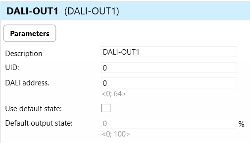
DALI Address:
The DALI Address parameter assigns a unique address to each DALI output channel on the RC3-610M device.
DALI devices, such as lighting fixtures, are identified and controlled based on their assigned DALI addresses.
Each DALI output channel can be configured with a specific address, allowing for individual control and addressing of connected DALI devices within the lighting system.
The DALI address parameter ensures proper communication and coordination between the RC3-610M device and the DALI lighting fixtures, facilitating precise control and management of the lighting environment.
Use Default State:
The "Use Default State" parameter determines whether the default state of the DALI output channel should be enforced in the event of no communication from the bus or central unit.
Enabling this functionality guarantees that the DALI channel automatically adopts its default state, pre-defined to a specific value.
Once activated, the DALI output channel will be adjusted to its default state, as specified by the Default Output State parameter.
Default Output State:
The Default Output State parameter outlines the predetermined state value of the DALI output channel when the "Use Default State" feature is enabled.
It determines whether, in the absence of communication from the bus or central unit, the DALI output channel should be configured to a specific "value."
Exports for iNELS Cloud and APP
Setting Up Control and Monitoring for iNELS Cloud and iNELS App
It is possible to control and monitor all the bus units in iNELS cloud and iNELS app. There are two stages to set up this function. Stage one is to do configuration in iDM3 and stage 2 is to do Configuration in iNELS cloud page and iNELS app.
Configuration in iDM3.
1. Unit and Parameter Selection:
Begin by accessing the iDM3 interface on your PC connected to CU. Navigate to the Device Manager section and carefully select the units and parameters you wish to control. This step is essential for determining what gets exported to the iNELS cloud and app.

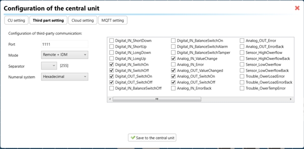
2. CU Configuration and Third-Party Settings :
After the above step, go to the CU configuration in the iDM3, and select the page for third-party settings.
Inside the third-party settings page, designate the port for cloud connection. Set the mode of operation and choose the numerical system as hexadecimal. Pay close attention to verifying and configuring all essential parameters for successful cloud export.
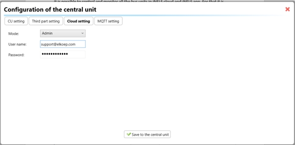
3. Cloud Settings:
Move on to the Cloud Settings section within iDM3.
Input the details of your iNELS cloud account. If you haven't created one, utilize the "New User" tab on the iNELS Cloud web page to establish a free account. (Inels Cloud - ElkoEP).
Select the mode and input the cloud account credentials. Save the project to the central unit to generate and store the export project file in the iNELS cloud account.
Configuration in iNELS cloud page and iNELS App.
1. Online Status Verification:
Once the cloud credentials and export settings in iDM3 are configured successfully, check the iNELS cloud account's Gateway section. Confirm that the Central Unit (CU) is online and that the export file has been automatically sent to the cloud under your account.
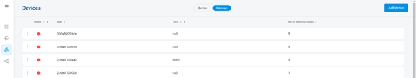
2. Device Creation in Cloud Platform:
In the cloud platform, you have to create new devices in order to control it remotely.
In the device tab, you will find the add device button, which can be used to associate export elements from IDM with the required types and icons.
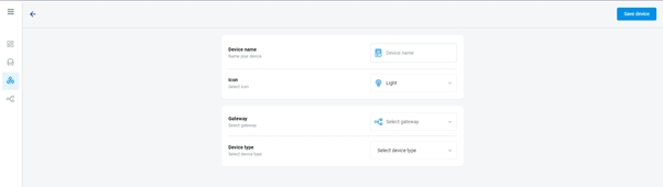
After entering any name of the device, you select the icon, the MAC address of the communication gateway (in this case CU3), a specific type of device and the address of a specific function and element from the iNELS BUS system.
In order to be able to use the iNELS application to control the devices from CU over the local network or the cloud, it is necessary to create a room for bus devices for each central unit and add the devices into the room.
Follow these steps meticulously to ensure a seamless configuration process for controlling and monitoring all bus units through iNELS cloud and iNELS app.
3rd Party Integration with iNELS BUS
3rd Party Integration (MQTT)
iNELS units support MQTT integration on central units CU3-07M, CU3-08M, CU3-09M, and CU3-10M. It is necessary to select the devices and parameters for 3rd party integration on the device manager in the iDM.
Please note that you have an MQTT broker (local or cloud) running in the installation for this integration.
After you have a working MQTT broker you need to configure iNELS Central units to communicate with it. If you have no knowledge of what MQTT is, you can learn about it from MQTT Essentials articles. https://www.hivemq.com/mqtt/
There is a pre-installed MQTT broker in the iNLES bridge, it can be used to connect the iNELS Central units for integration in your projects.
Configuration in iDM3: Select units of 3rd Party integration.
Unit and Parameter Selection:
Begin by accessing the iDM3 interface on your PC connected to CU. Navigate to the Device Manager section and carefully select the units and parameters you wish to control. This step is essential for determining what gets exported to the 3rd party integration via MQTT.

2. CU Configuration and Third-Party Settings :
After the above step, go to the CU configuration in the iDM3, and select the page for third party settings.
Inside the third-party settings page, designate the port for third-party connection. Set the mode of operation and choose the numerical system as hexadecimal. Pay close attention to verifying and configuring all essential parameters for successful third-party integration.
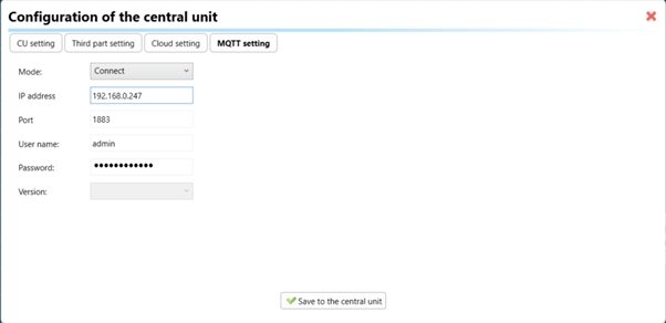
3. MQTT Settings:
Move on to the MQTT Settings section within iDM3.
Input the details of your MQTT broker.
Select the mode and input the broker credentials such as IP, port username and password. Save the project to the central unit.
MQTT payload
For MQTT payload description please refer the link below. https://wiki.inels.com/v/inels-bus/3rd-party-integration/mqtt-payload-description-of-inels-bus-devices
Appendices
Last updated