FA3-612M
Fancoil controller
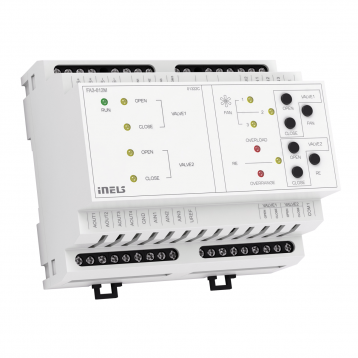
Overview of devices
An overview of the product design and usage. Also contain circuit diagrams, terminal details, etc.,
Key Features:
FA3-612M is a unit (actuator) designed to control fancoil units using analogue/digital inputs and analog/relay outputs.
Analog Inputs: These inputs are used for temperature, voltage, or current measurements. They can also utilize a reference voltage (URef).
Digital Inputs: The digital inputs are galvanically isolated with positive logic (Sink) and accept voltages in the range of 24-230 V AC/DC.
Analog Outputs: The unit provides analog outputs in the range of 0-10 V.
Connection to Installation BUS: The unit can be connected to an installation BUS, allowing for integration into larger control systems and communication with other devices on the network.
Control Buttons: Buttons are provided for the closing and opening of the valve, fan, and heating relay.
LED Indicators: LEDs on the front panel indicate the status of various components and conditions, including FAN, RE (relay), VALVE1, VALVE2, OVER-RANGE, and OVERLOAD.
Mounting: The FA3-612M unit is designed for mounting into a switchboard on a DIN rail according to the EN60715 standard. This mounting configuration offers convenience and compatibility with standard switchboard installations.
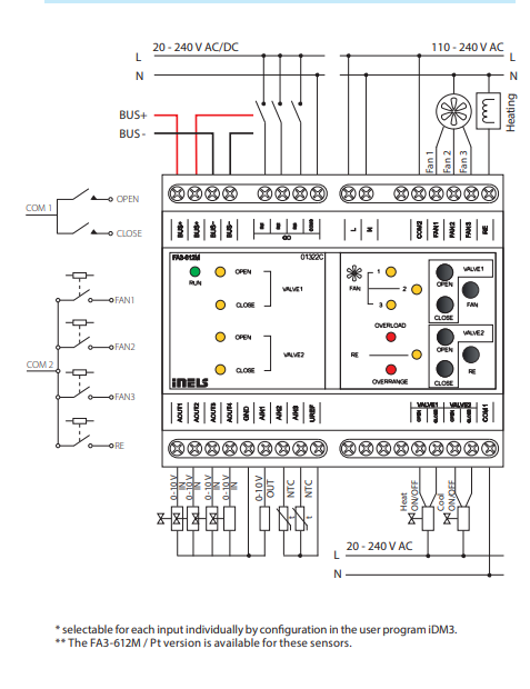
Exemplary circuit diagram/ Wiring Diagram
Compatibility chart ( CU, minimal FW version and Integration)
The chart illustrates the compatibility between the fancoil controller and various central units, firmware versions, and integration options.
1
CU3-01M
02.83.00
NA
NA
2
CU3-02M
02.83.00
NA
NA
3
CU3-07M
02.83.00
Yes
Yes
4
CU3-08M
02.83.00
Yes
Yes
6
CU3-09M
Preparation
Preparation
Preparation
7
CU3-10M
Preparation
Preparation
Preparation
Programming in iDM
Introduction
iNELS Design Manager, or IDM3, is for programming iNELS units. This software serves as the platform for configuring device parameters, defining functions, and executing the programming required for iNELS units.
Device parameters, such as sensor range and thresholds, backlights, and operational modes, can be easily adjusted within the IDM3.
The process of programming in IDM3 typically involves defining functions and establishing logical connections between different devices. This allows for the creation of automation scenarios and the implementation of intelligent control strategies.
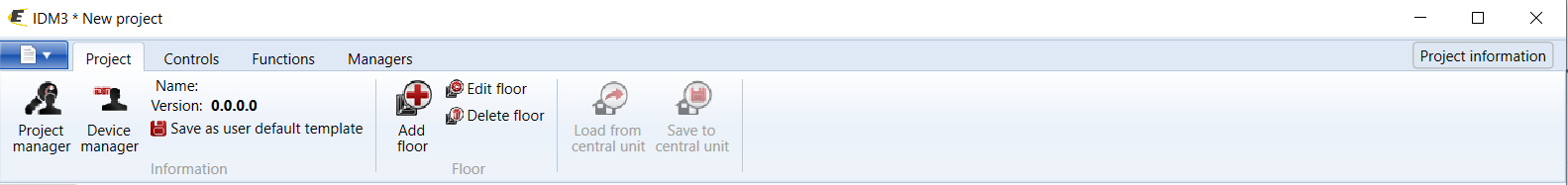
Starting up
Select the "blue control icon" as shown in Fig 1 > Clicking on the option "New project from default template“ allows you to create a new project from a predefined template.
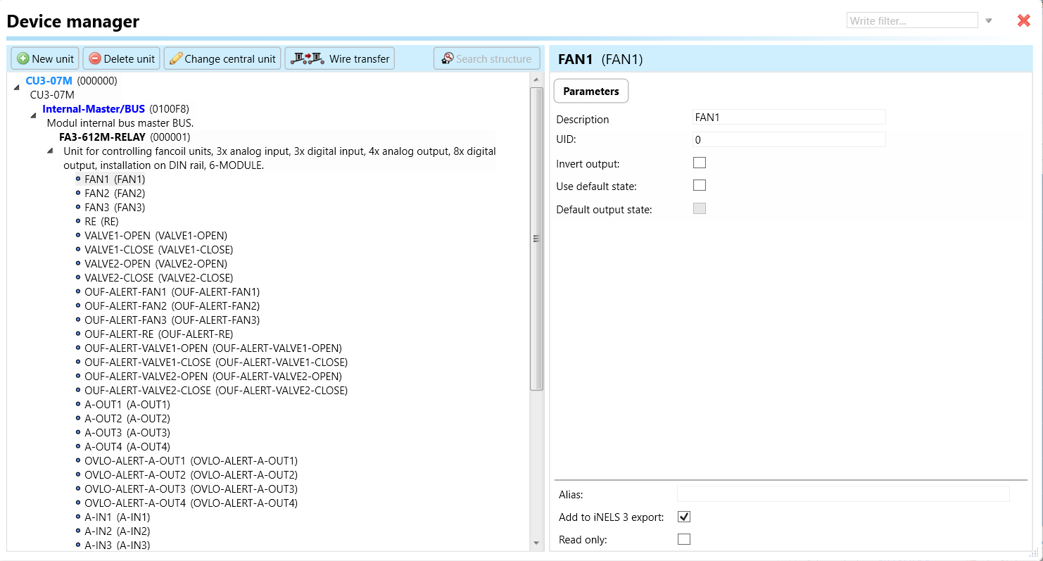
Select the "Device manager" (Fig 1)> Add "New unit "> Select the central unit > Add "New unit">Select the "Internal-Master/ BUS"> Add "New unit "> Add the devices> Click on the devices to see the "Parameters".
Parameters:
Parameters in the iNELS devices refer to the measurable factors or characteristics that define the behavior or performance of the device. These could include electrical properties, physical dimensions, environmental conditions, and various other specifications depending on the type of device.
These are settings specific to individual devices within your automation system.The specific parameters of the FA3-612M in the iDM as shown in Fig.2
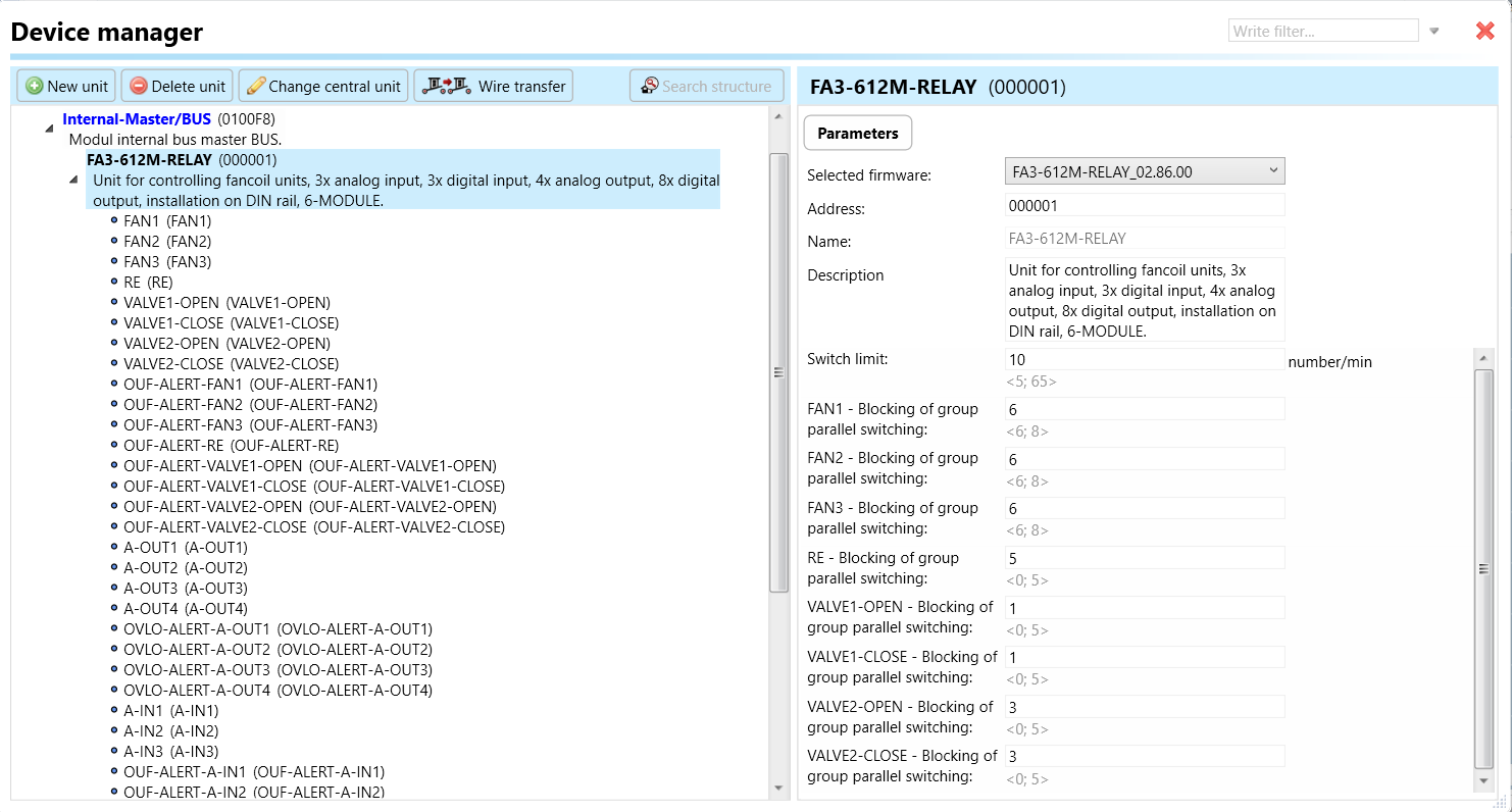
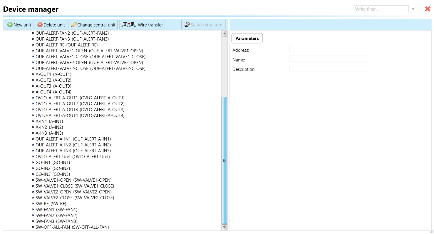
Clicking on the FA3-612M (Fig.2), will navigate to selected firmware, unit address, name, and description, along with other parameters as described below :
It is important to add the device address for proper communication with the unit. The Hexadecimal device address can be find from the device.
Switch limit: Switch limit refers to the maximum number of times that a switch or relay within the FA3-612 device can be reliably activated (closed) or deactivated (opened).
FAN 1-3: Blocking Group Parallel Switching: This parameter refers to the control of up to three fans connected in parallel. When activated, it allows for the simultaneous operation of these fans, typically used for providing air circulation in a fan coil unit. Blocking group parallel switching means that these fans are controlled together, operating in parallel without any one fan blocking the operation of the others.
RE (Relay): Blocking Group Parallel Switching: This parameter controls relay operations in a blocking group parallel switching manner. The relay(s) is responsible for various functions within the system, such as activating or deactivating heating elements, controlling pumps, or managing other electrical components. Blocking group parallel switching ensures that the relays operate collectively without blocking each other's function.
VALVE 1, 2 OPEN: Blocking Group Parallel Switching: This parameter controls the opening of valves 1 and 2 in a blocking group parallel switching configuration. Valves are typically used for regulating the flow of fluids, such as water or refrigerant, in HVAC systems. When activated, this parameter ensures that both valves open simultaneously, allowing for fluid flow without any one valve blocking the operation of the others.
VALVE 1, 2 CLOSE: Blocking Group Parallel Switching: Similar to the previous parameter, this controls the closing of valves 1 and 2 in a blocking group parallel switching configuration. When activated, both valves close simultaneously, ensuring that fluid flow is halted without any one valve blocking the operation of the others.
These parameters are essential for coordinating the operation of fans and valves in a synchronized manner, ensuring efficient and reliable control of air and fluid flow within the system managed by the FA3-612M unit.
1. FAN 1-3: These parameters control the operation of up to three fans. Each parameter corresponds to a specific fan. When activated, it triggers the respective fan to operate.
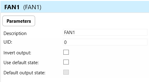
Invert Output: This parameter determines whether the output state of the fan controls is inverted or not. When activated, it causes the opposite effect on the output state. For instance, if "Invert Output" is enabled for FAN 1, activating the control signal would turn the fan off, and deactivating it would turn the fan on.
Use Default State: In the context of combined units, the term "default state" pertains to the pre-established or initial condition that the actuator adopts in the absence of communication from the bus or central unit. Enabling this function ensures that the relay automatically assumes its default state, which is set to OFF.
Default Output State: Upon choosing the "use default state" option, you will be prompted to specify the default output state. This refers to the pre-established or initial condition that the actuator adopts when there is no communication from the bus stop or central unit. Upon selecting this function, the relay will transition to its default output state, which, in this case, is set to ON.
2. RE: This parameter controls relay operation. It likely activates or deactivates a relay responsible for a specific function within the system.
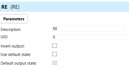
Invert Output: This parameter determines whether the RELAY is inverted or not. When activated, it causes the opposite effect on the output state.
Use Default State: In the context of combined units, the term "default state" pertains to the pre-established or initial condition that the actuator adopts in the absence of communication from the bus or central unit. Enabling this function ensures that the relay automatically assumes its default state, which is set to OFF.
Default Output State: Upon choosing the "use default state" option, you will be prompted to specify the default output state. This refers to the pre-established or initial condition that the actuator adopts when there is no communication from the bus stop or central unit. Upon selecting this function, the relay will transition to its default output state, which, in this case, is set to ON.
3. VALVE 1, 2 OPEN: These parameters control the opening of valves 1 and 2. When activated, they trigger the respective valves to open, allowing fluid flow.
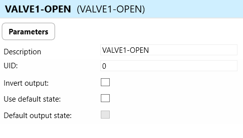
4. VALVE 1, 2 CLOSE: These parameters control the closing of valves 1 and 2. When activated, they trigger the respective valves to close, stopping fluid flow.
5. OUF ALERT FAN 1-3: These parameters indicate alerts related to the operation of fans 1-3. They signal an "Over-Current Fault" condition for the corresponding fan.
6. OUF ALERT VALVE 1, 2 OPEN: These parameters indicate alerts related to the opening of valves 1 and 2. They signal an "Over-Current Fault" condition for the respective valve opening operation.
7. OUF ALERT VALVE 1, 2 CLOSE: These parameters indicate alerts related to the closing of valves 1 and 2. They signal an "Over-Current Fault" condition for the respective valve closing operation.
8. A-OUT 1-4: A-OUT1-4 refers to the analog output channels of the FA3-612 actuator. These outputs provide voltage signals in the range of 0-10V, typically used for controlling external devices or systems such as fan speed controllers or valve actuators.
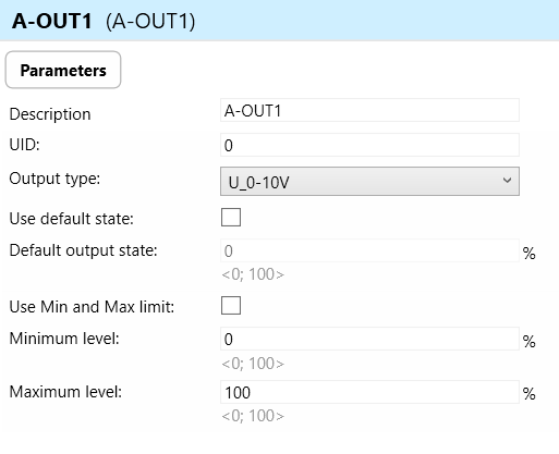
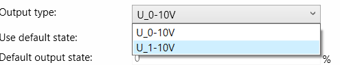
Output Types: Analog voltage signals in the range of 0-10V.
Use Default State: Specifies whether the analog outputs should default to a predefined state upon startup or initialization of the FA3-612 device.
Default Output State: Defines the default voltage level of the analog outputs when the FA3-612 is powered on or reset.
Use Min and Max Limit: Indicates whether the analog outputs should be constrained within minimum and maximum limits to prevent overdriving or exceeding the specified voltage range.
Minimum Level: Specifies the minimum voltage level that can be outputted by the analog outputs.
Maximum Level: Specifies the maximum voltage level that can be outputted by the analog outputs.
9. OVLO-ALERT-A-OUT1-4: These parameters indicate alerts related to the analog output channels. They signal an "Over-Voltage" fault condition for the respective analog output channel.
10. A-IN1-3: These parameters likely represent analog input channels. They may receive voltage or current signals from sensors or other devices for monitoring purposes.
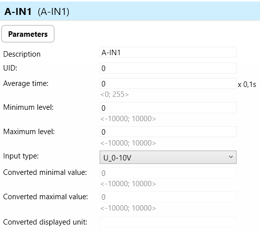

Parameters for A-IN1-3 (Analog Inputs 1-3):
a. Average Time: Average time refers to the duration over which the analog inputs integrate or average multiple readings to calculate a representative value. This parameter helps to smooth out fluctuations in input signals caused by noise or rapid changes in the measured quantity.
b. Minimum Level: Minimum level refers to the lowest threshold of the measured quantity that the analog inputs are capable of detecting and accurately measuring. This parameter ensures that the inputs operate within their specified range and can reliably capture the entire range of the measured quantity.
c. Maximum Level: Maximum level refers to the highest threshold of the measured quantity that the analog inputs are capable of detecting and accurately measuring. This parameter establishes the upper limit of the input signal range, beyond which the inputs may saturate or lose accuracy.
d. Input Types: Input types specify the nature of the measured quantity that the analog inputs are designed to handle. In the case of the FA3-612 device, the analog inputs may be used for temperature, voltage, or current measurements.
e. Converted Minimum Value: Converted minimum value refers to the lowest possible value of the measured quantity after conversion from the raw analog input signal to engineering units (e.g., temperature in degrees Celsius).
f. Converted Maximal Value: Converted maximal value refers to the highest possible value of the measured quantity after conversion from the raw analog input signal to engineering units (e.g., temperature in degrees Celsius).
g. Converted Displayed Unit: Converted displayed unit specifies the unit of measurement used to display the converted analog input signal in the user interface or output. For example, temperature measurements may be displayed in degrees Celsius or Fahrenheit.
11. OUF-ALERT-A-IN 1-3: These parameters indicate alerts related to the analog input channels. They likely signal an "Over-Current Fault" condition for the respective analog input channel.
12. OVLO-ALERT-Uref: This parameter indicates an alert related to the reference voltage (URef). It likely signals an "Over-Voltage" fault condition for the reference voltage.
13. GO-IN1-3: These parameters represent digital input channels. They may receive signals from switches or sensors for various control.
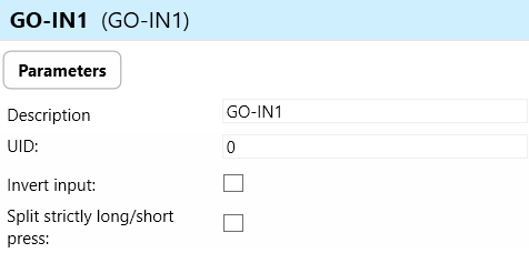
a. Invert Input: Invert input refers to a feature that allows users to invert the logic of the digital input signal received by the GO-IN 1-3 inputs. When enabled, a logic HIGH signal (e.g., 1 or ON) at the input would be interpreted as a logic LOW signal (e.g., 0 or OFF), and vice versa.
b. Split Strictly Long/Short Press: Split strictly long/short press refers to a feature that distinguishes between long and short press events on the digital input of the FA3-612 device.
Long Press: Holding the digital input signal for a predefined duration (longer than a specified threshold) before releasing it triggers a long press event.
Short Press: Briefly activating the digital input signal without holding it for the predefined duration triggers a short press event.
14. SW-VALVE1, 2-OPEN: These parameters initiate switch controlled opening of valves 1 and 2.
15. SW-VALVE1, 2-CLOSE: These parameters initiate switch-controlled closing of valves 1 and 2.
16. SW-RE: This parameter initiates switch-controlled relay operation.
17. SW-FAN1-3: These parameters initiate switch-controlled operation of fans 1-3.
18. SW-OFF-ALL-FAN: This parameter initiates switch-controlled shutdown of all fans.
These parameters collectively enable comprehensive control and monitoring capabilities for the FA3-612M device, allowing for precise management of fans, valves, relays, and other components within the system it controls.
Exports for iNELS Cloud and APP
Setting Up Control and Monitoring for iNELS Cloud and iNELS App
It is possible to control and monitor all the bus units in iNELS cloud and iNELS app. There are two stages to set up this function. Stage one is to do configuration in iDM3 and stage 2 is to do Configuration in iNELS cloud page and iNELS app.
Configuration in iDM3.
1. Unit and Parameter Selection:
Begin by accessing the iDM3 interface on your PC connected to CU. Navigate to the Device Manager section and carefully select the units and parameters you wish to control. This step is essential for determining what gets exported to the iNELS cloud and app.

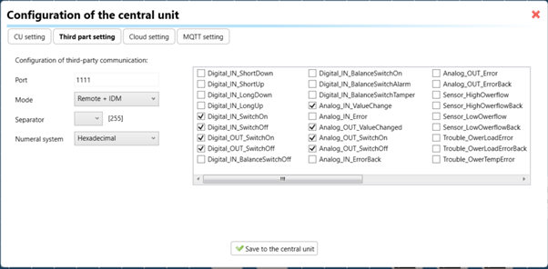
2. CU Configuration and Third-Party Settings :
After the above step, go to the CU configuration in the iDM3, and select the page for third-party settings.
Inside the third-party settings page, designate the port for cloud connection. Set the mode of operation and choose the numerical system as hexadecimal. Pay close attention to verifying and configuring all essential parameters for successful cloud export.
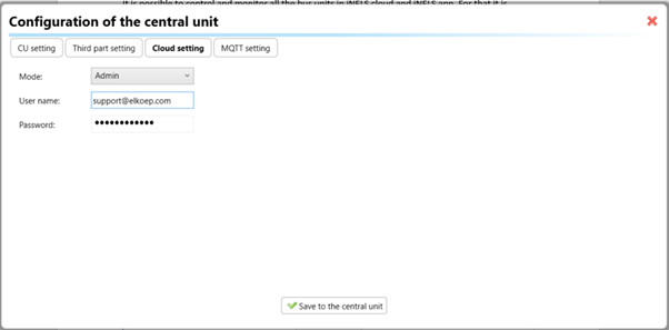
3. Cloud Settings:
Move on to the Cloud Settings section within iDM3.
Input the details of your iNELS cloud account. If you haven't created one, utilize the "New User" tab on the iNELS Cloud web page to establish a free account. (Inels Cloud - ElkoEP).
Select the mode and input the cloud account credentials. Save the project to the central unit to generate and store the export project file in the iNELS cloud account.
Configuration in iNELS cloud page and iNELS App.
1. Online Status Verification:
Once the cloud credentials and export settings in iDM3 are configured successfully, check the iNELS cloud account's Gateway section. Confirm that the Central Unit (CU) is online and that the export file has been automatically sent to the cloud under your account.
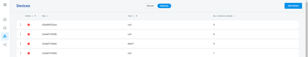
2. Device Creation in Cloud Platform:
In the cloud platform, you have to create new devices in order to control it remotely.
In the device tab, you will find the add device button, which can be used to associate export elements from IDM with the required types and icons.

After entering any name of the device, you select the icon, the MAC address of the communication gateway (in this case CU3), a specific type of device and the address of a specific function and element from the iNELS BUS system.
In order to be able to use the iNELS application to control the devices from CU over the local network or the cloud, it is necessary to create a room for bus devices for each central unit and add the devices into the room.
Follow these steps meticulously to ensure a seamless configuration process for controlling and monitoring all bus units through iNELS cloud and iNELS app.
3rd Party Integration with iNELS BUS
3rd Party Integration (MQTT)
iNELS units support MQTT integration on central units CU3-07M, CU3-08M, CU3-09M, and CU3-10M. It is necessary to select the devices and parameters for 3rd party integration on the device manager in the iDM.
Please note that you have an MQTT broker (local or cloud) running in the installation for this integration.
After you have a working MQTT broker you need to configure iNELS Central units to communicate with it. If you have no knowledge of what MQTT is, you can learn about it from MQTT Essentials articles. https://www.hivemq.com/mqtt/
There is a pre-installed MQTT broker in the iNLES bridge, it can be used to connect the iNELS Central units for integration in your projects.
Configuration in iDM3: Select units of 3rd Party integration.
Unit and Parameter Selection:
Begin by accessing the iDM3 interface on your PC connected to CU. Navigate to the Device Manager section and carefully select the units and parameters you wish to control. This step is essential for determining what gets exported to the 3rd party integration via MQTT.
2. CU Configuration and Third-Party Settings :
After the above step, go to the CU configuration in the iDM3, and select the page for third party settings.
Inside the third-party settings page, designate the port for third-party connection. Set the mode of operation and choose the numerical system as hexadecimal. Pay close attention to verifying and configuring all essential parameters for successful third-party integration.
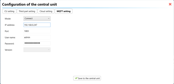
3. MQTT Settings:
Move on to the MQTT Settings section within iDM3.
Input the details of your MQTT broker.
Select the mode and input the broker credentials such as IP, port username and password. Save the project to the central unit.
MQTT payload
For MQTT payload description please refer the link below. https://wiki.inels.com/v/inels-bus/3rd-party-integration/mqtt-payload-description-of-inels-bus-devices
Appendices
Provide any optional, supplementary information that may help in providing a more comprehensive understanding of the product feature.
Last updated