Two-point regulator
Principle
The principle of the two-point regulator is illustrated in Fig.
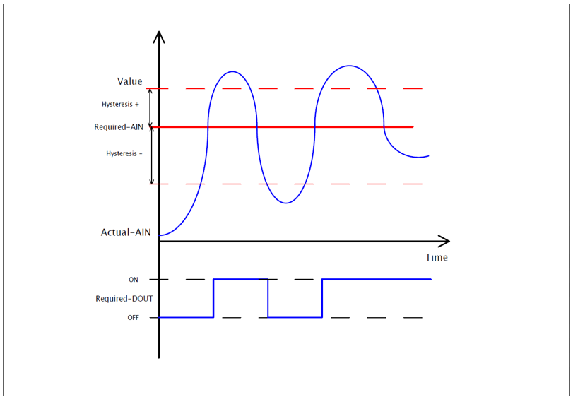
The function of two-point regulator.
Increasing the current value provided by "Actual-AIN" above the limit set by "Required-AIN", incremented by a positive hysteresis value labeled "Hysteresis +", triggers the digital output "Required-DOUT" to switch to "ON" (logical 1).
Decreasing the current value provided by "Actual-AIN" below the limit set by "Required-AIN", decremented by a negative hysteresis value labeled "Hysteresis -", causes the digital output "Required-DOUT" to switch to "OFF" (logical 0).
Configuring in iDM.
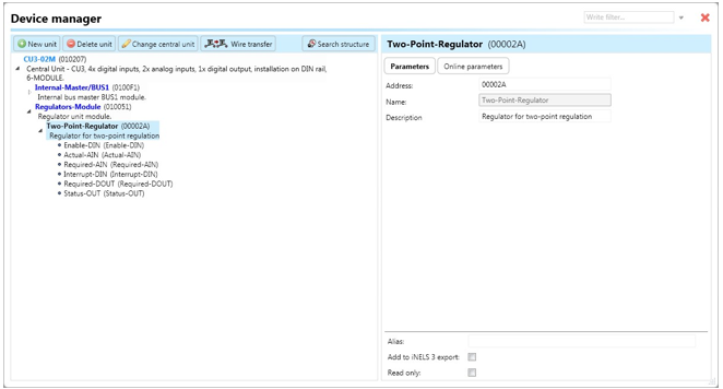
Select the "Device manager" > Add "New unit "> Select the central unit > Add "New unit">Select the "Regulators-Module".
Add “Regulators-Module”, with a fixed hexadecimal address value of “010051”. The system can store only one module of this type.
Then, add a "Two-Point-Regulator" (refer to Fig. a ). The system allows for a maximum of 256 regulators.
Devices
Enable-DIN: Digital input responsible for initiating regulator control by setting the device state to "ON" using the function call "Digital – On".
Actual-AIN: Analog input responsible for processing the current value of the selected quantity, such as temperature, provided by a function call like "Analog – copy" from a temperature input or controller.
Required-AIN: Analog input responsible for processing the required value of the selected quantity, such as temperature, provided by a function call like "Analog – copy" from a controller or system integer. The value stored in the system integer is divided by 100 during copying.
Interrupt-DIN: Digital input responsible for interrupting the regulator function by setting the device state to "OFF", thereby turning off the output "Required-DOUT".
Required-DOUT: Digital output connectable to an actuator, such as a relay.
Status-OUT: Output state generating actions further in the system:
"Status ON": Regulator is turned on.
"Status OFF": Regulator is turned off.
"Status error actual": Input "Actual-AIN" encountered an error.
"Status end error actual": Error of "Actual-AIN" disappeared.
"Status error required 1": Input "Required-AIN" encountered an error.
"Status end error required 1": Error of "Required-AIN" disappeared.
"Status interrupt": Regulator has been stopped by input "Interrupt-DIN".
"Status end interrupt": Regulator function has been restored after interrupting by input "Interrupt-DIN".
Parameters
Address: Hexadecimal address of the unit related to the regulator – the value must not collide with any other existing one.
Name: Allows the user to define some description or the name of the unit.
The two-point regulator contains the following online parameters accessible by clicking on the sub-tab "Online parameters" and then clicking on the pencil icon in the top-right corner of the Device Manager (refer to Fig.):
Hysteresis -: Value represented as the range deducted from the current value of the measured quantity while the current value is decreasing. The value distinguishes a step of 0.01(i.e. 25.81, 25.82, etc.).
Hysteresis +: Value represented as the range added to the current value of the measured quantity while the current value is increasing. The value also distinguishes a step of 0.01(i.e. 25.81, 25.82, etc.).
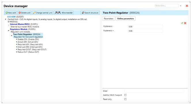
Buttons "v" (green tick) or "x" (red cross) can be used to confirm or cancel the definition of "Online parameters".
Note: After initially saving the project to the central unit, it is possible to modify online parameters without needing to save the project again. Changes can be saved by clicking on the "v" button.
Last updated