Three-point regulator
Principle
The principle of a three-point regulator can be described using a diagram shown in fig.
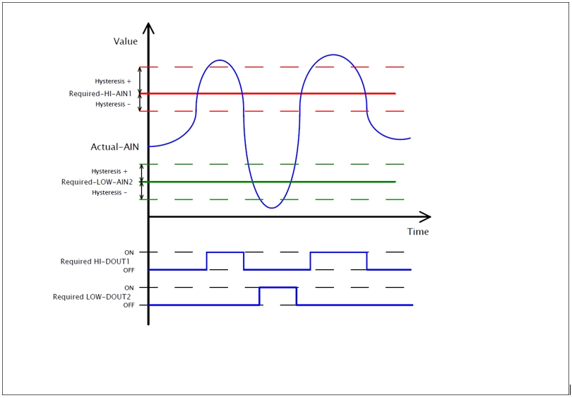
Increasing the current value provided by "Actual-AIN" above the limit provided by "Required-HI-AIN1", increased by a positive value of hysteresis "Hysteresis +", changes the state of digital output "Required-HI-DOUT1" to "ON" (logical 1).
Decreasing the current value provided by "Actual-AIN" below the limit provided by "Required-HI-AIN1", decreased by a negative value of hysteresis "Hysteresis -", changes the state of digital output "Required-HI-DOUT1" to "OFF" (logical 0).
Another decreasing of the current value provided by "Actual-AIN" below the limit provided by "Required-LOW-AIN2", decreased by a negative value of hysteresis "Hysteresis -", changes the state of digital output "Required-LOW-DOUT2" to "ON" (logical 1).
Increasing the current value provided by "Actual-AIN" above the limit provided by "Required-LOW-AIN2", increased by a positive value of hysteresis "Hysteresis +", changes the state of digital output "Required-LOW-DOUT2" to "OFF" (logical 0).
Configuring in iDM
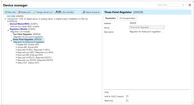
Select the "Device manager" > Add "New unit "> Select the central unit > Add "New unit"> Select the "Regulators-Module".
Add “Regulators-Module”, with a fixed hexadecimal address value of “010051”. The system can store only one module of this type.
Afterwards, add a new three-point regulator called "Three-Point-Regulator" (see fig.). The maximal amount of regulators in the system is set to 256.
Devices
The regulator unit contains the following devices:
Enable-DIN: A digital input responsible for running or stopping the regulator by setting the device state to “ON” (via function call “Digital – On”), initiating regulator control.
Actual-AIN: An analog input responsible for processing the current value of the selected quantity (e.g., temperature) obtained through a function call “Analog - copy” from a temperature input or controller.
Required-Hi-AIN1: An analog input responsible for processing the required high value of the selected quantity (e.g., temperature) obtained through a function call "Analog - copy" from a controller or system integer. The value stored in the system integer is divided by 100 during copying.
Required-Low-AIN2: An analog input responsible for processing the required low value of the selected quantity (e.g., temperature) obtained through a function call "Analog - copy" from a controller or system integer. The value stored in the system integer is divided by 100 during copying.
Interrupt-DIN: A digital input responsible for interrupting the regulator function by setting the device state to “OFF” (if it has appeared in state “ON” before), turning off the output “Required-DOUT”, and triggering a state change of “Status-OUT”.
Required-Hi-DOUT1: A digital output connected to an actuator (e.g., relay), switched to state “ON” when the input value of “Actual-AIN” exceeds the input value of “Required-Hi-AIN1” increased by a particular hysteresis. It is switched to state “OFF” when the input value of “Actual-AIN” goes below the input value of “Required-Hi-AIN1” decreased by a particular hysteresis.
Required-Low-DOUT2: A digital output connected to an actuator (e.g., relay), switched to state “ON” when the input value of “Actual-AIN” goes below the input value of “Required-Low-AIN2” decreased by a particular hysteresis. It is switched to state “OFF” when the input value of “Actual-AIN” exceeds the input value of “Required-Low-AIN2” also decreased by a particular hysteresis.
Status-OUT generates the following actions that can be used further in the system:
“Status ON”: Indicates that the regulator is turned on.
“Status OFF”: Indicates that the regulator is turned off.
“Status error actual”: Indicates that the input “Actual-AIN” encountered some error.
“Status end error actual”: Indicates that the error of the “Actual-AIN” disappeared.
“Status error required 1”: Indicates that the input “Required-Hi-AIN1” encountered some error.
“Status end error required 1”: Indicates that the error of the “Required-Hi-AIN1” disappeared.
“Status error required 2”: Indicates that the input “Required-Low-AIN2” encountered some error.
“Status end error required 2”: Indicates that the error of the “Required-Low-AIN2” disappeared.
“Status interrupt”: Indicates that the regulator has been stopped by input “Interrupt-DIN”.
“Status end interrupt”: Indicates that the regulator function has been restored after interrupting by input “Interrupt-DIN”.
Parameters
Address: Hexadecimal address of the unit related to the regulator. The value must not collide with any other existing one (any possible address).
Note: Allows the user to define some description or the name of the unit.
Two point regulator contains the following online parameters accessible by clicking on the sub tab “Online parameters” and clicking on the icon of the pencil in the top-right corner of Device manager (Fig):

“Hysteresis – Required Hi AIN1”: Represents the range applied to “Required-Hi-AIN1” and deducted from the current value of the measured quantity while the current value is decreasing. The value distinguishes a step of 0.01 (e.g., 25.81, 25.82, etc.).
“Hysteresis + Required Hi AIN1”: Represents the range applied to “Required-Hi-AIN1” and added to the current value of the measured quantity while the current value is increasing. The value distinguishes a step of 0.01 (e.g., 25.81, 25.82, etc.).
“Hysteresis – Required Low AIN2”: Represents the range applied to “Required-Low-AIN2” and deducted from the current value of the measured quantity while the current value is decreasing. The value distinguishes a step of 0.01 (e.g., 25.81, 25.82, etc.).
“Hysteresis + Required Low AIN2”: Represents a positive value representing the range added to the current value of the measured quantity while the current value is increasing. The value distinguishes a step of 0.01 (e.g., 25.81, 25.82, etc.).
Buttons “v” (green tick) or “x” (red cross) can confirm or cancel defining of “Online parameters”.
Last updated