Heating regulator
Principle
The principle of regulator function is the same as that of the two-point regulator. Refer Two-point regulator
The two outputs of the regulator change state to "ON" when the current temperature goes below the required temperature decreased by hysteresis.
The regulator changes state to "OFF" when the current temperature exceeds the required temperature increased by hysteresis.
Heating regulator includes two additional safety functions compared to the two-point regulator. The first function detects the exceeding of the critical temperature of floor heating, causing both outputs to change state to "OFF" even if the required temperature has not been reached.
The second function detects a decrease in current temperature below the antifreeze temperature, causing both outputs of the regulator to change states to "ON" even if the required temperature has been exceeded and the critical temperature of floor heating has not been exceeded.
Configuring in iDM
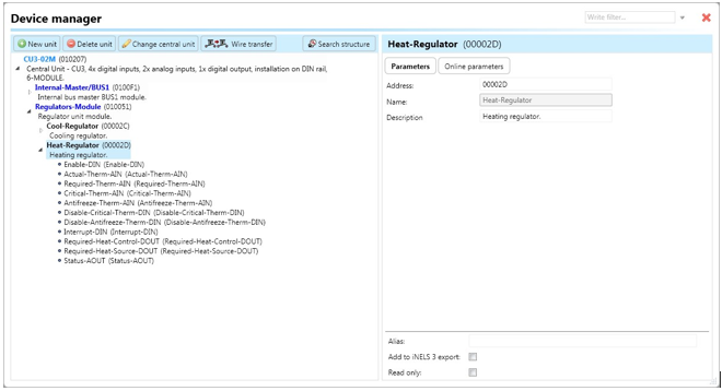
Select the "Device manager" > Add "New unit "> Select the central unit > Add "New unit">Select the "Regulators-Module".
Add “Regulators-Module”, with a fixed hexadecimal address value of “010051”. The system can store only one module of this type.
Afterwards, add a new heating regulator called “Heat- Regulator“ (see fig.).
The maximal amount of regulators in the system is set to 256.
Devices
Regulator unit contains the following devices:
Enable-DIN: Digital input responsible for running / stopping the regulator by setting device state to “ON“ (using function call “Digital – On“), which initiates regulator control.
Actual-Therm-AIN: Analog input responsible for processing of current temperature (e.g. value provided by function call “Analog – copy“ from output “Actual-Therm-AOUT” of the controller).
Required-Therm-AIN: Analog input responsible for processing of required temperature (e.g. value provided by function call “Analog – copy“ from output “Required- Therm-AOUT” of the controller or system integer). The value stored in the system integer is divided by 100 in case of copying.
Critical-Therm-AIN: Analog input responsible for processing of required temperature (e.g. value provided by function call “Analog – copy“ from output “Critical-Therm-AOUT” of the controller or temperature input getting current temperature of floor heating).
Antifreeze-Therm-AIN: Analog input responsible for processing of antifreeze temperature (e.g. value provided by function call “Analog – copy“ from output “Antifreeze- Therm-AOUT” of the controller). The value stored in the system integer is divided by 100 in case of copying.
Disable-Critical-Therm-DIN: Digital input responsible for turning off detection of critical temperature exceeding. Changing state to “ON” (e.g. by wire with a function call “Digital – On“), stops detection of critical temperature exceeding.
Disable-Maximal-Therm-DIN: Digital input responsible for turning off detection of decrease of current temperature below antifreeze temperature. Changing state to “ON” (e.g. by wire with a function call “Digital – On“), stops detection of current temperature going under antifreeze temperature.
Interrupt-DIN: Digital input responsible for temporarily interrupting the regulator function by setting device state to “OFF“ (if it has appeared in state “ON” before) by turning off the output “Required-DOUT”.
Required-Heat-Control-DOUT: Digital output responsible for controlling of the cooling, connectable to actuator (SA) controlling of the valve (state 0/1) 230V or 24V attached on radiator or floor heating distributor or valve control unit.
Required-Heat-Source-DOUT: Digital output responsible for controlling of heating supply, connectable to actuator (SA) controlling directly a heating supply (e.g. boiler).
Status-AOUT: Output state generating following actions that can be used further in the system:
“Status ON“: Regulator is turned on.
“Status OFF“: Regulator is turned off.
“Status error actual“: Input “Actual-Therm-AIN“ encountered some error.
“Status end error actual“: Error of the “Actual-Therm-AIN“ disappeared.
“Status error required 1“: Input “Required-Therm-AIN“ encountered some error.
“Status end error required 1“: Error of the “Required-Therm-AIN“ disappeared.
“Status interrupt“: Regulator has been stopped by input “Interrupt-DIN“.
“Status end interrupt“: Regulator function has been restored after interrupting by input “Interrupt-DIN“.
“Status error critical“: Input “Critical-Therm-AIN“ encountered some error.
“Status end error critical“: Error of “Critical-Therm-AIN“ disappeared.
“Status error antifreeze“: Input “Antifreeze-Therm-AIN“ encountered some error.
Status end error antifreeze“: Error of “Antifreeze-Therm-AIN“ disappeared.
Parameter
Address: Hexadecimal address of the unit related to the regulator – the value must not collide with any other existing one (any possible address).
Note: Allows the user to define some description or the name of the unit.
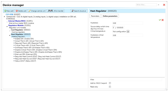
Two point regulator contains the following online parameters accessible by clicking on the subtab “Online parameters“ and clicking on the icon of a pencil in the top-right corner of Device manager (Fig):

Hysteresis: Value represented as the range applied to current temperature, whose value is changing. The value distinguishes a step 0.01°C (i.e. 25.81, 25.82, etc.).
Source delay switch time: Defined time lag used between two actions, i.e., Valve opening and heating supply (with a pump) turning on.
Critical temperature: This field stores a temperature (value) representing a limit which cannot be exceeded by floor heating function. The value distinguishes a step 0.01°C (i.e. 25.81, 25.82, etc.). In case that critical temperature does not have to be detected, therefore leave option “NotConfiguration“ (as it is) or change the option using a dropdown menu.
Hysteresis-critical temperature: Stores a temperature represented by value (range) applied to current temperature, whose value is changing. The value distinguishes a step 0.01°C (i.e. 25.81, 25.82, etc.).
Buttons “v“ (green tick) or “x“ (red cross) can confirm or cancel defining of “Online parameters”.
Note: After the initial saving of the project to the central unit, it is possible to modify online parameters without the need of resaving the project, and saving it by clicking on button “v”.
Cooling regulator online parameters.
Last updated