Fan-coil regulators
Configuration in iDM
Configuration of the cooling regulator can be done via Device Manager:
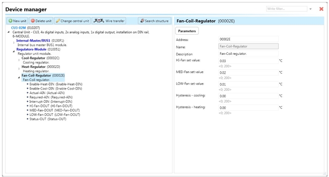
Select the "Device manager" > Add "New unit "> Select the central unit > Add "New unit">Select the "Regulators-Module".
Add “Regulators-Module”, with a fixed hexadecimal address value of “010051”. The system can store only one module of this type.
Afterwards, add a new fan-coil regulator called “Fan-coil-Regulator” (refer to Fig). The maximum amount of regulators in the system is set to 256.

Devices
Clicking on the Fan-coil regulator will navigate to following devices as described below:
Enable-Heat-DIN : i.e. digital input responsible for running/ stopping of the regulator in heating mode by setting device state to “ON“ (using function call “Digital – On“), which initiates regulator control.
Enable-Cool-DIN: i.e. digital input responsible for running / stopping of the regulator in cooling mode by setting device state to “ON“ (using function call “Digital – On“), which initiates regulator control.
Actual-AIN: Analog input responsible for processing the current value of the selected quantity. For example, it can process temperature provided by a function call "Analog - copy" from a temperature input or output like "Actual-Therm-AOUT".
Required-AIN: Analog input responsible for processing the required value of the selected quantity. For instance, it can process temperature provided by a function call "Analog - copy" from a controller or system integer. Note that the value stored in the system integer is divided by 100 when copied.
Interrupt-DIN: Digital input responsible for interrupting the regulator function by setting the device state to “OFF”. It stops the regulator function (if it was in the "ON" state before) by turning off all outputs.
HI-Fan-DOUT: Digital output for setting the fastest speed of the fan.
MED-Fan-DOUT: Digital output for setting the medium speed of the fan.
LOW-Fan-DOUT: Digital output for setting the slowest speed of the fan.
Status-OUT: Output state generating various actions that can be used further in the system:
"Status ON": Indicates that the regulator is turned on.
"Status OFF": Indicates that the regulator is turned off.
"Status error actual": Indicates that the input “Actual-AIN” encountered some error.
"Status end error actual": Indicates that the error of the “Actual-AIN” has disappeared.
"Status error required 1": Indicates that the input “Required-AIN” encountered some error.
"Status end error required 1": Indicates that the error of the “Required-AIN” has disappeared.
"Status interrupt": Indicates that the regulator has been stopped by input “Interrupt-DIN”.
"Status end interrupt": Indicates that the regulator function has been restored after interrupting by input “Interrupt-DIN”.
Parameters
Address: Hexadecimal address of the unit related to the regulator. The value must not collide with any other existing address.
Name: Allows the user to define some description or the name of the unit.
HI-Fan set value: This field stores a value representing the difference between the current and required temperature. If such a difference exists, the regulator turns on the output “HI-Fan-DOUT”.
MED-Fan set value: This field stores a value representing the difference between the current and required temperature. If such a difference exists, the regulator turns on the output “MED-Fan-DOUT”.
LOW-Fan set value: This field stores a value representing the difference between the current and required temperature. If such a difference exists, the regulator turns on the output “LOW-Fan-DOUT”.
Hysteresis - cooling: Stores a temperature represented by a value (range) applied to the current temperature, whose value is changing (increasing or decreasing) in cooling mode. The value distinguishes a step of 0.01°C (e.g., 25.81, 25.82, etc.).
Hysteresis - heating: Stores a temperature represented by a value (range) applied to the current temperature, whose value is changing (increasing or decreasing) in heating mode. The value distinguishes a step of 0.01°C (e.g., 25.81, 25.82, etc.).
Fan-coil regulator function
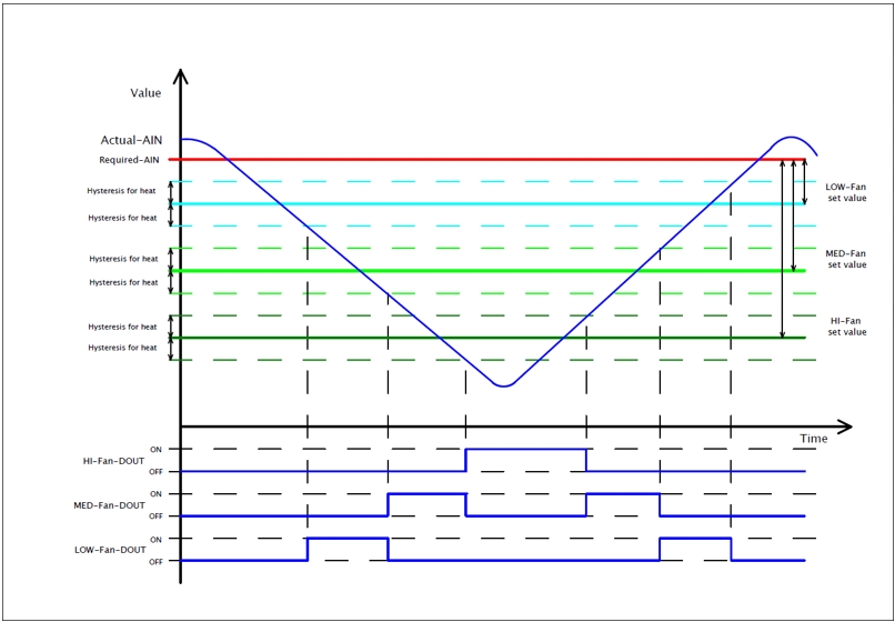
The fan-coil regulator function related to heating is described using the following steps:
Decreasing the current value provided by “Actual-AIN” under the limit provided by the “LOW-Fan set value”, whose value is decreased by the hysteresis for heat.
This change switches the state of digital output “LOW-Fan-DOUT” to “ON” (logical 1).
Another decrease under the limit provided by the “MED-Fan set value” changes the state of digital output “MED-Fan-DOUT” to “ON”, while “LOW-Fan-DOUT” switches to “OFF”(logical 0).
Another decrease under the limit provided by the “HI-Fan set value” changes the state of digital output “HI-Fan-DOUT” to “ON”, while “MED-Fan-DOUT” switches to “OFF”.
Increasing the current value above the limit provided by the “HI-Fan set value” changes the state of digital output “HI-Fan-DOUT” to “OFF”, while “MED-Fan-DOUT” switches to “ON”.
Another increase above the limit provided by the “MED-Fan set value” changes the state of digital output “MED-Fan-DOUT” to “OFF”, while “LOW-Fan-DOUT” switches to “ON”.
Another increase above the limit provided by “LOW-Fan set value” changes the state of digital output “LOW-Fan-DOUT” to “OFF”.

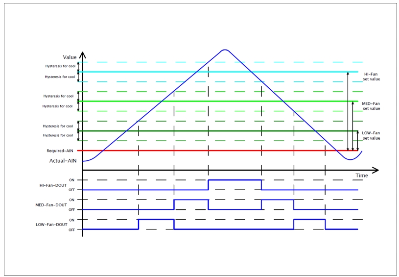
The fan-coil regulator function related to cooling is described using the following steps:
Increasing the current value provided by “Actual-AIN” above the limit provided by “Low-Fan set value” changes the state of digital output “LOW-Fan-DOUT” to “ON”(logical 1).
Another increase above the limit provided by “MED-Fan set value” whose value is increased by value of hysteresis “Hysteresis for cool“, changes the state of digital output “MED-Fan-DOUT” to “ON”, while “LOW-Fan-DOUT” switches to “OFF”(logical 0).
Another increase of current value provided by “Actual-AIN“ above the limit provided by “HI-Fan set value” whose value is increased by value of hysteresis “Hysteresis for cool“ changes the state of digital output “HI-Fan-DOUT” to “ON”(logical 1), while “MED-Fan-DOUT” switches to “OFF”(logical 0).
Decreasing the current value by “Actual-AIN under the limit provided by “HI-Fan set value” whose value is decreased by value of hysteresis “Hysteresis for cool“, changes the state of digital output “HI-Fan-DOUT” to “OFF”(logical 0), while “MED-Fan-DOUT” switches to “ON”(logical 1).
Another decrease under the limit provided by “MED-Fan set value” changes the state of digital output “MED-Fan-DOUT” to “OFF”, while “LOW-Fan-DOUT” switches to “ON”.
Another decrease under the limit provided by “LOW-Fan set value” changes the state of digital output “LOW-Fan-DOUT” to “OFF”(logical 0).

Last updated