Cooling regulator
Principle
The principle of regulator function is the same as at two point regulator. Refer Two-point regulator
Cooling regulator contains extra safety function compared to two point regulator.
This safety function is an action related to the monitoring of exceeding maximal temperature.
When the regulator detects an exceeding of the maximal temperature, it turns both outputs to state “ON“.
This action occurs even in case of exceeding the required temperature.
Configuring in iDM
Select the "Device manager" > Add "New unit "> Select the central unit > Add "New unit"> Select the "Regulators-Module".
Add “Regulators-Module”, with a fixed hexadecimal address value of “010051”. The system can store only one module of this type.
Afterwards, add a new cooling regulator called “Cool-Regulator“.
The maximal amount of regulators in the system is set to 256.
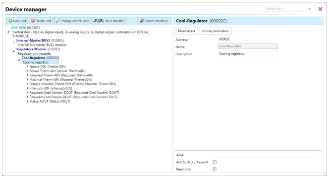
Enable-DIN: Digital input for starting or stopping the regulator by setting the device state to "ON" using the function call "Digital – On".
Actual-Therm-AIN: Analog input for processing the current temperature, typically obtained from the output "Actual-Therm-AOUT" of the controller.
Required-Therm-AIN: Analog input for processing the required temperature, typically obtained from the output "Required-Therm-AOUT" of the controller or system integer. The stored integer value is divided by 100 during copying.
Maximal-Therm-AIN: Analog input for processing the maximal temperature, typically obtained from the output "Maximal-Therm-AOUT" of the controller or system integer. The stored integer value is divided by 100 during copying.
Disable-Maximal-Therm-DIN: Digital input for disabling the detection of maximal temperature exceeding. Changing the state to "ON" stops the detection process.
Interrupt-DIN: Digital input for temporarily interrupting the regulator function by setting the device state to "OFF", thereby turning off the output "Required-DOUT".
Required-Cool-Control-DOUT: Digital output for controlling cooling, connectable to an actuator (SA) managing the cooling unit.
Required-Cool-Source-DOUT: Digital output for controlling cooling supply, connectable to an actuator (SA) directly managing the cooling supply.
"Status-OUT": Output state generating actions for further use in the system:
"Status ON": Regulator is turned on.
"Status OFF": Regulator is turned off.
"Status error actual": Error encountered in input "Actual-Therm-AIN".
"Status end error actual": Error in "Actual-Therm-AIN" disappeared.
"Status error required 1": Error encountered in input "Required-Therm-AIN".
"Status end error required 1": Error in "Required-Therm-AIN" disappeared.
"Status interrupt": Regulator stopped by input "Interrupt-DIN".
"Status end interrupt": Regulator function restored after interruption by input "Interrupt-DIN".
"Status error maximal": Error encountered in input "Maximal-Therm-AIN".
"Status end error maximal" : Error in "Maximal-Therm-AIN" disappeared.
Parameters
Address: Hexadecimal address of the unit related to the regulator, ensuring it does not collide with any other existing addresses.
Note: Field allowing the user to define a description or name for the unit.
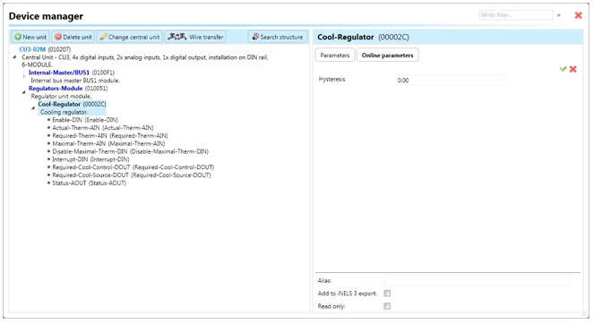
Two-point regulator contains the following online parameters accessible by clicking on the subtab "Online parameters" and then clicking on the icon of a pencil in the top-right corner of the Device manager:
Hysteresis: Value represented as the range applied to the current value as it changes. The value distinguishes steps of 0.01 (e.g., 25.81, 25.82, etc.).
Buttons "v" (green tick) or "x" (red cross) can confirm or cancel the definition of online parameters.
Note: After initially saving the project to the central unit, it is possible to modify online parameters without saving the project again. Changes can be saved by clicking on the "v" button.
Last updated