> For the complete documentation index, see [llms.txt](https://wiki.inels.com/llms.txt). Markdown versions of documentation pages are available by appending `.md` to page URLs; this page is available as [Markdown](https://wiki.inels.com/inels-bus/inels-design-manager-idm3/hotel-room-object.md).
# Hotel-Room Object
Comprehensive, step-by-step manual for the Hotel-Room Object that you can use directly on the Hotel projects
*Hospitality installations — guest rooms, PMS integration, and iNELS Harmony.*
***
## 1. What it is
The **Hotel-Room Object** is a **virtual device** inside the CU3 central unit, designed specifically for hotel and hospitality projects. It aggregates all **guest, room and climate functions** into a single object, so the information is available to reception software, a **PMS** (Property Management System) or a **BMS** without handling dozens of separate signals.
Everything about a guest room — occupied or empty, do-not-disturb, temperature, window open — is unified in one place.
### Why it matters
* Instead of configuring dozens of signals separately, all values are **consolidated in one object**
* PMS/BMS integration needs only **one MQTT topic per room**, which minimises complexity and errors
* Housekeeping sees **MUR and DND** instantly in the PMS — no wasted trips to rooms
* Maintenance can monitor **HVAC performance** (temperature, humidity, valve status) remotely
* Reception gets **real-time visibility** of guest presence, alarms and scenes
* Fewer manual processes → lower staffing costs and higher efficiency
* Works equally for **small boutique hotels** and **large multi-building resorts**
* Each CU3 handles **more than one** Hotel-Room object, all with the same interface
* Use the iNELS Hotel Reservation Software (iHRS) or connect a **third-party PMS/BMS**
* The open MQTT/JSON interface suits cloud platforms, custom dashboards and mobile apps
> ### Rooms will not appear in iNELS Harmony without this object
>
> This is the one that catches people out. You can wire a guest room perfectly — lights, heating, card reader, everything working — and **the room still will not be discovered by iNELS Harmony**.
>
> Harmony finds rooms by looking for Hotel-Room objects. No object, no room. The installation works locally and looks finished, but the hotel's management layer sees nothing.
>
> **On any project that will use Harmony, add the Hotel-Room object from the start.** Retrofitting it across eighty rooms after commissioning is a long, avoidable job.
***
## 2. Main features
| Group | What it covers |
| ----------------------- | ------------------------------------------------------------------------ |
| **Guest & room status** | Occupancy, Do Not Disturb (DND), Make Up Room (MUR), Butler/service call |
| **Climate control** | Actual temperature, humidity, dew point, setpoints, correction |
| **HVAC control** | Mode, plan, fan speed |
| **Room events** | Door/window status, card events |
| **Scenes** | Welcome scene + 5 customisable room scenes |
| **MQTT integration** | One topic per room, JSON payload |
| **Bidirectional** | Both **read status** and **write control** are supported |
***
## 3. Adding it to a project
You need a current **iDM version** for the Hotel object to be available, and current **CU3 firmware** ([Chapter 25](/inels-bus/inels-design-manager-idm3/idm3-firmware-update-manager.md)).
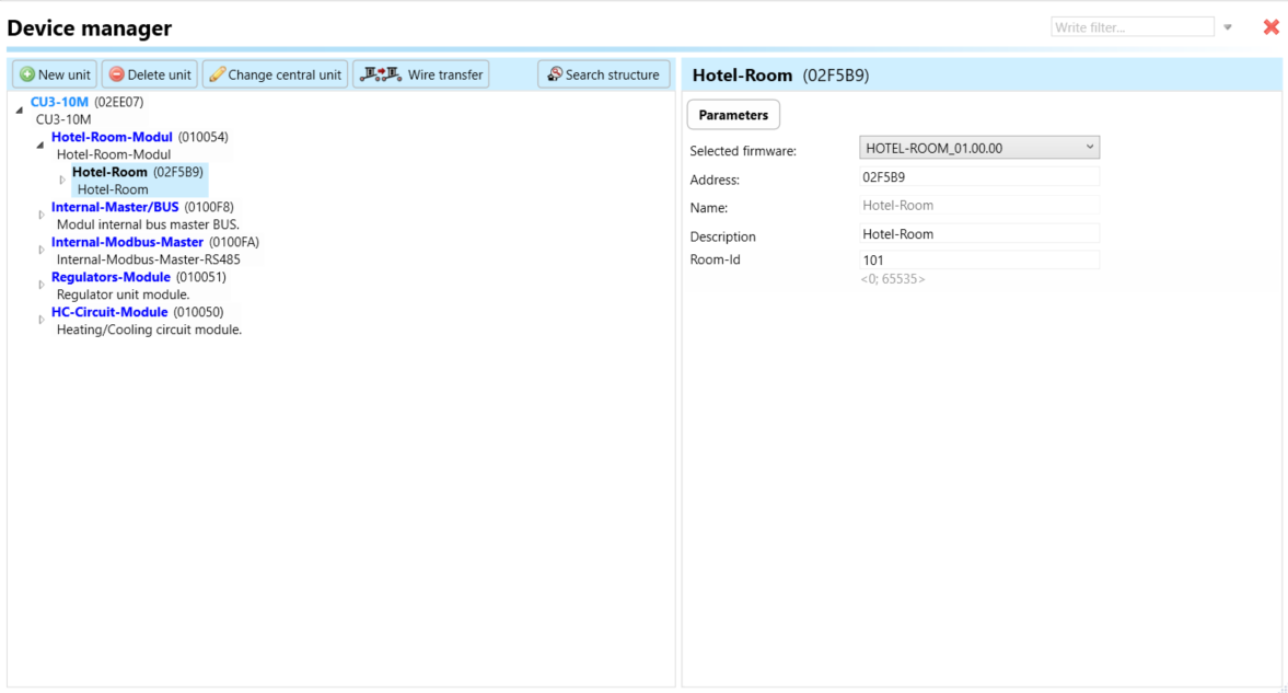
The structure is two levels:
```
CU3
└── Hotel-Room-Modul ← the module: add once
├── Hotel-Room Room-Id 101 ← one per guest room
├── Hotel-Room Room-Id 102
└── Hotel-Room Room-Id 103
```
**One `Hotel-Room` unit per physical guest room.** A forty-room floor is forty units under one module.
### Step 1 — Add the module
1. **Project** ribbon tab → **Device manager**.
2. Select the **central unit** → **New slave**.
3. Choose **`Hotel-Room-Modul`** → **OK**.
The module has no parameters. It is a container.
### Step 2 — Add a room
1. **Select the `Hotel-Room-Modul`.**
2. **New unit** → **`Hotel-Room`** → **OK**.
3. Set its **Description** to something a human recognises — `Room 101`.
### Step 3 — Set the parameters
Select the `Hotel-Room` unit. In **Parameters** you will see:
| Parameter | Range | What it is |
| ---------------------- | ------------------------- | ------------------------------------------ |
| **Address** | assigned by iDM3 | Unique identifier of the object in the CU3 |
| **Name / Description** | text | For project documentation |
| **Room-Id** | `0 – 65535` (default `1`) | Links the object to the hotel room number |
**Enter the hotel's actual room number as Room-Id.** Room 101 gets `101`; room 1204 gets `1204`.
> **Room-Id is not the Address.** They are different fields with different jobs, and the PMS integrator needs both:
| | Set by | Used by |
| ----------- | ------ | ---------------------------------------- |
| **Address** | iDM3 | the central unit, and the **MQTT topic** |
| **Room-Id** | you | the PMS, Harmony, and the hotel |
> **Get Room-Id right the first time.** It is how the PMS and Harmony identify the room. Changing it later means the management system loses track of that room until its own configuration is updated to match.
> **Rooms with no number.** Give staff rooms, plant rooms and suites a consistent scheme — `9001` upwards, say — rather than leaving them at the default `1`. Two objects sharing Room-Id `1` is a problem you will find late.
Repeat steps 2 and 3 for every room.
***
## 4. Device structure — the 23 datapoints
Expand a `Hotel-Room` unit and you will find 23 devices. They are ordinary iNELS objects: wire them, use them in conditions, read them in Monitor. The names in brackets are what you will see in the device tree.
### Guest & room status
| Datapoint | Carries |
| ------------- | -------------------------- |
| **Occupancy** | Guest in room (true/false) |
| **DND** | Do Not Disturb |
| **MUR** | Make Up Room |
| **Buttler** | Service call |
> **"Buttler" is spelled that way in the software** — with two t's. You are looking at the right datapoint.
### Climate control
| Datapoint | Carries |
| ---------------------------- | ---------------------------------------------- |
| **Actual-Therm-AOUT** | Actual temperature |
| **Required-Heat-Therm-AOUT** | Required heat setpoint |
| **Required-Cool-Therm-AOUT** | Required cool setpoint |
| **Set-Therm-AIN** | The temperature the guest or PMS is asking for |
| **Correction** | Calibration offset |
| **Humidity-AOUT** | Relative humidity |
| **Dew-Point-AOUT** | Dew point |
> **Read the suffixes.** `-AOUT` datapoints are values the object **publishes** — what the room is doing. `-AIN` datapoints are written **into** the object — what someone is asking for.
**Dew point matters more than it sounds.** In humid climates, cooling below the dew point causes condensation on chilled surfaces. Hotels commonly use this datapoint to limit how far cooling can go.
### HVAC control
| Datapoint | Carries |
| ------------------------ | -------------------------------- |
| **Control-IN** | Heat / Cool / Off |
| **Control-Mode-IN** | Plan / Manual / Eco / Dry etc. |
| **Control-Plan-IN** | Base / Holiday / Public Holiday |
| **Control-Fan-Speed-IN** | Low / Medium / High / Auto / Off |
The numeric values behind each of these are in the **Payload reference** at the end of this page.
### Room events
| Datapoint | Carries |
| ----------------- | ------------- |
| **Door-Status** | Open / Closed |
| **Window-Status** | Open / Closed |
### Scenes
| Datapoint | Carries |
| ----------------------- | ----------------------------------- |
| **Welcome-Scene** | Triggered when a guest first enters |
| **Scene1** – **Scene5** | Five further scenes, customisable |
***
## 5. Linking to a Heat/Cool controller
The Hotel-Room object holds the guest's *request*. A **Heat/Cool area (HCA)** is what regulates the room ([Chapter 10](/inels-bus/inels-design-manager-idm3/tutorial-heating-and-cooling.md)). They have to be joined.
1. Add a **Controller for Heating and Cooling (HCA)** in **System manager** → **Heat/Cool areas** tab.
2. Under **Connections**, select the **Hotel-Room object** for this room.
iDM will **automatically create internal wires** between the Hotel-Room object and the HCA. The climate data — actual temperature, required heat setpoint, required cool setpoint, correction, humidity, dew point — is wired for you.
> **Important:** You must still wire the HCA outputs (**Fan regulator**, **Valve regulator**) to the **physical output relays or analog outputs** controlling the HVAC equipment.
>
> The automatic linking connects the object to the *controller*, not the controller to the *hardware*. A room where the guest can set a temperature, the PMS shows it correctly, and nothing physically happens is almost always this step, left undone.
Repeat per room — eighty rooms means eighty Heat/Cool areas.
***
## 6. Wiring it to the room hardware
The automatic link covers climate. Everything else you wire yourself, using the ordinary actor → function → consumer model ([Chapter 2](/inels-bus/inels-design-manager-idm3/how-programming-works-in-idm3.md)).
### Occupancy from a card holder
| Actor | Action | Function | Consumer |
| ----------------- | ----------------------- | ------------- | ------------- |
| Card holder input | `Digital IN switch ON` | `DIGITAL_ON` | **Occupancy** |
| Card holder input | `Digital IN switch OFF` | `DIGITAL_OFF` | **Occupancy** |
Then use **Occupancy** as an actor for everything that should follow the guest:
| Actor | Action | Function | Consumer |
| ------------- | ----------------------- | ------------------------------------- | ----------------- |
| **Occupancy** | `Digital IN switch ON` | `DIGITAL_ON` | **Welcome-Scene** |
| **Occupancy** | `Digital IN switch OFF` | `DIGITAL_GROUP_OFF` | room lights group |
| **Occupancy** | `Digital IN switch OFF` | `HEATING_COOLING_SWITCH_TO_FAVORITE1` | the room's HCA |
That last wire is where a hotel saves most of its energy: an empty room falls back to setback temperature automatically.
### DND, MUR and butler from the guest panel
Use a **GSB3** glass switch — a **GSB3-60** or **GSB3-90**, for example — as the bedside or entrance panel, with one button per guest function.
| Actor | Action | Function | Consumer |
| ------------- | ---------------------- | ---------------- | ----------------------- |
| GSB3 button 1 | `Short down` | `DIGITAL_SWITCH` | **DND** |
| GSB3 button 2 | `Short down` | `DIGITAL_SWITCH` | **MUR** |
| GSB3 button 3 | `Short down` | `DIGITAL_ON` | **Buttler** |
| **DND** | `Digital IN switch ON` | `DIGITAL_ON` | GSB3 button 1 backlight |
> **Drive the backlights from the datapoint, not the button.** Guests need to see whether DND is on. Taking the indication from the **DND** datapoint means the lamp always shows the real state — including when housekeeping or the PMS clears it remotely, which a button-driven indicator would miss entirely.
> **The older EST3 and EHT3 hotel panels are obsolete.** They still appear in the unit list so you can service existing installations, but do not specify them for new work. Use a GSB3 or current equivalent.
### Door and window
| Actor | Action | Function | Consumer |
| -------------- | ---------------------- | ------------ | ----------------- |
| Door contact | `Digital IN switch ON` | `DIGITAL_ON` | **Door-Status** |
| Window contact | `Digital IN switch ON` | `DIGITAL_ON` | **Window-Status** |
**Window-Status** is worth wiring even where the hotel has not asked for it: the HCA can suspend heating while a window is open, which pays for the contact quickly.
### Scenes
Wire **Welcome-Scene** and **Scene1**–**Scene5** to lighting groups, blinds or the television. Because they are datapoints on the object, the PMS can trigger them too — so a scene can be fired by the front desk as easily as by the guest.
### Useful patterns
| Goal | How |
| -------------------------------- | ------------------------------------------------------------------- |
| Setback when the guest leaves | **Occupancy** off → `HEATING_COOLING_SWITCH_TO_FAVORITE1` |
| No housekeeping while DND is on | Condition: **Restriction value** — **DND** `=` OFF |
| Stop cooling below dew point | Condition comparing **Dew-Point-AOUT** against the cooling setpoint |
| Heating off with a window open | **Window-Status** as a condition, or the HCA's window handling |
| Lights off when the room empties | **Occupancy** off → `DIGITAL_GROUP_OFF` on the room lighting group |
| Welcome on first entry | **Occupancy** on → `DIGITAL_ON` on **Welcome-Scene** |
***
## 7. MQTT integration
#### Topic Structure
* **Status (publish)**
```
inels/status//Hotelroom/
```
* **Set (subscribe)**
```
inels/set//Hotelroom/
```
#### Example Status Payload
```json
{
"timestamp": "2025-08-25T18:45:52Z",
"room_id": "1",
"occupancy": false,
"dnd": false,
"mur": true,
"buttler": true,
"temperature": {
"current": 23.5,
"set_heat": 22,
"set_cool": 24,
"correction": 1
},
"humidity": 55,
"dew_point": 14.8,
"control": "Heat",
"control_mode": "Plan",
"control_plan": "Base",
"fan_speed": "Low",
"door_status": "Closed",
"window_status": "Closed",
"scenes": {
"welcome_scene": true,
"scene_1": false,
"scene_2": true,
"scene_3": false,
"scene_4": true,
"scene_5": false
}
}
```
***
#### Example Set Payload
```json
{
"dnd": true,
"mur": false,
"buttler": false,
"temperature": {
"set_heat": 21,
"set_cool": 24,
"correction": 0
},
"control": "Cool",
"control_mode": "Manual",
"control_plan": "Holiday",
"fan_speed": "Auto",
"door_status": "Closed",
"window_status": "Closed",
"scenes": {
"welcome_scene": false,
"scene_1": true,
"scene_2": false,
"scene_3": false,
"scene_4": false,
"scene_5": true
}
}
```
### Payload reference
#### Fan Speed
| Key | Name | Description |
| --- | ---- | --------------------------- |
| 0 | Low | Fan at low speed |
| 1 | Med | Fan at medium speed |
| 2 | Hi | Fan at high speed |
| 3 | Auto | Automatic fan speed control |
| 4 | Off | Fan switched off |
#### HVAC control
| Key | Name | Description |
| --- | ---- | ------------------- |
| 0 | Cool | Cooling mode active |
| 1 | Heat | Heating mode active |
| 2 | Off | System switched off |
#### HVAC Modes
| Key | Name | Description |
| --- | ---- | ------------------- |
| 0 | Cool | Cooling mode active |
| 1 | Heat | Heating mode active |
| 2 | Off | System switched off |
Control Modes
| Key | Name | Description |
| --- | --------- | ---------------------------- |
| 0 | Plan | Follow scheduled plan |
| 1 | Favorite1 | User-defined favorite mode 1 |
| 2 | Favorite2 | User-defined favorite mode 2 |
| 3 | Favorite3 | User-defined favorite mode 3 |
| 4 | Favorite4 | User-defined favorite mode 4 |
| 5 | Fan | Fan-only mode |
| 6 | Eco | Energy-saving mode |
| 7 | Manual | Manual override mode |
| 8 | Dry | Dehumidification mode |
#### Plan Control Modes
| Key | Name | Description |
| --- | -------------- | ---------------------------------- |
| 0 | Base | Base (default) plan |
| 64 | Holiday | Holiday plan |
| 128 | Public Holiday | Public holiday plan (special case) |
***
## 8. If a room does not appear in iNELS Harmony
| Check | |
| --------------------------------------- | ------------------------------------------------------------------------------------- |
| Does the room have a `Hotel-Room` unit? | No object, no room — see §1 |
| Is the **Room-Id** set and unique? | Two rooms sharing an Id will not both appear |
| Was the project uploaded? | **Save to central unit** |
| Is MQTT enabled and connected? | [Chapter 22](/inels-bus/inels-design-manager-idm3/idm3-central-unit-configuration.md) |
| Is the CU3 firmware current? | [Chapter 25](/inels-bus/inels-design-manager-idm3/idm3-firmware-update-manager.md) |
***
## 9. Before handover
* [ ] Every guest room has its own `Hotel-Room` unit
* [ ] Every **Room-Id** matches the hotel's real room number, and none are duplicated
* [ ] Each room has a **Heat/Cool area** linked under **Connections**
* [ ] Fan and valve regulator outputs are **wired to physical hardware**
* [ ] Occupancy, DND, MUR and door/window are wired and tested
* [ ] Guest panel is a current unit (GSB3 or similar), not an obsolete EST3/EHT3
* [ ] Guest panel backlights follow the datapoints, not the buttons
* [ ] MQTT is enabled and the rooms appear in Harmony
* [ ] The PMS integrator has a table of **Address ↔ Room-Id**
***
**See also:** [Chapter 10 — Heating and cooling](/inels-bus/inels-design-manager-idm3/tutorial-heating-and-cooling.md) · [Chapter 20 — System manager](/inels-bus/inels-design-manager-idm3/idm3-system-manager-reference.md) · [Chapter 24 — External systems](/inels-bus/inels-design-manager-idm3/idm3-external-systems-mqtt-modbus-cloud.md)