DLS3-1
Light intensity sensor
Overview of devices
An overview of the product design and usage. Includes circuit diagrams, terminal details, etc.,

Key Features:
Sensing Functionality: The DLS3-1 luminescence sensor detects the current luminescence at its installation point.
Communication Interfaces:
Equipped with two communication interfaces:
iNELS BUS installation, DALI (up to 4 DMD3-1 or DLS3-1 units can be used on one DALI bus).
Light Intensity Information:
Provides information about current light intensity, facilitating tasks such as maintaining constant luminescence. Allows adjustment of artificial light based on natural light contribution, potentially reducing energy consumption.
Versatile Application: Suitable for various environments including residential projects, commercial spaces, offices, manufacturing plants, and warehouses.
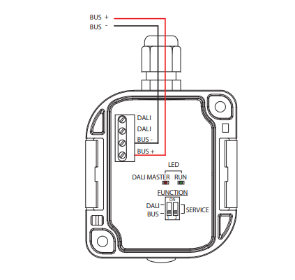
Installation Guidelines: Recommended installation orientation with the luminescence sensor facing downward and avoiding direct radiation exposure.
Communication Interface Setup: Configuration of communication interface using DIP switches:
- Upper position: DALI communication interface
- Lower position: iNELS communication interface.
Power Supply: Powered directly via iNELS BUS installation (nominal 27 V DC) or DALI BUS (nominal 16 V DC).
Configuration Software: Configurable via iNELS3 Designer & Manager software, enabling customization of desired functions based on detected illumination.
Sensing Range: Sensing range spans from 1 to 100,000 lux, accommodating various lighting conditions.
Outdoor Installation Capability: Supplied in IP65 rating, suitable for outdoor installation, ensuring durability and reliability even in challenging environmental conditions.
Exemplary circuit diagram/ Wiring Diagram
Compatibility chart ( CU, minimal FW version and Integration)
The chart illustrates the compatibility between detector and various central units, firmware versions, and integration options.
1
CU3-01M
01.34.00
NA
NA
2
CU3-02M
01.34.00
NA
NA
3
CU3-07M
Preparation
NA
NA
4
CU3-08M
Preparation
NA
NA
6
CU3-09M
Preparation
Preparation
Preparation
7
CU3-10M
Preparation
Preparation
Preparation
Programming in iDM
Introduction
iNELS Design Manager, or IDM3, is for programming iNELS units. This software serves as the platform for configuring device parameters, defining functions, and executing the programming required for iNELS units.
Device parameters, such as sensor range and thresholds, backlights, and operational modes, can be easily adjusted within the IDM3.
The process of programming in IDM3 typically involves defining functions and establishing logical connections between different devices. This allows for the creation of automation scenarios and the implementation of intelligent control strategies.
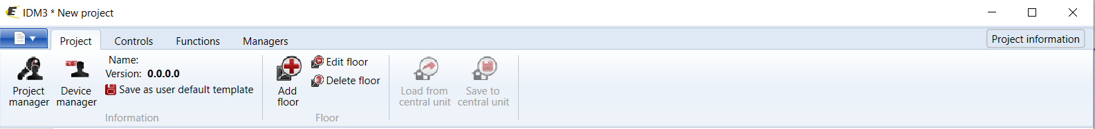
Starting up
Select the "blue control icon" as shown in Fig 1 > Clicking on the option "New project from default template“ allows you to create a new project from a predefined template.
Select the "Device manager" (Fig 1)> Add "New unit "> Select the central unit > Add "New unit">Select the "Internal-Master/ BUS"> Add "New unit "> Add the devices> Click on the devices to see the "Parameters".
Parameters:
Parameters in the iNELS devices refer to the measurable factors or characteristics that define the behavior or performance of the device. These could include electrical properties, physical dimensions, environmental conditions, and various other specifications depending on the type of device.
These are settings specific to individual devices within your automation system.
The specific parameters of the DLS3-1 in the iDM as shown in Fig.2
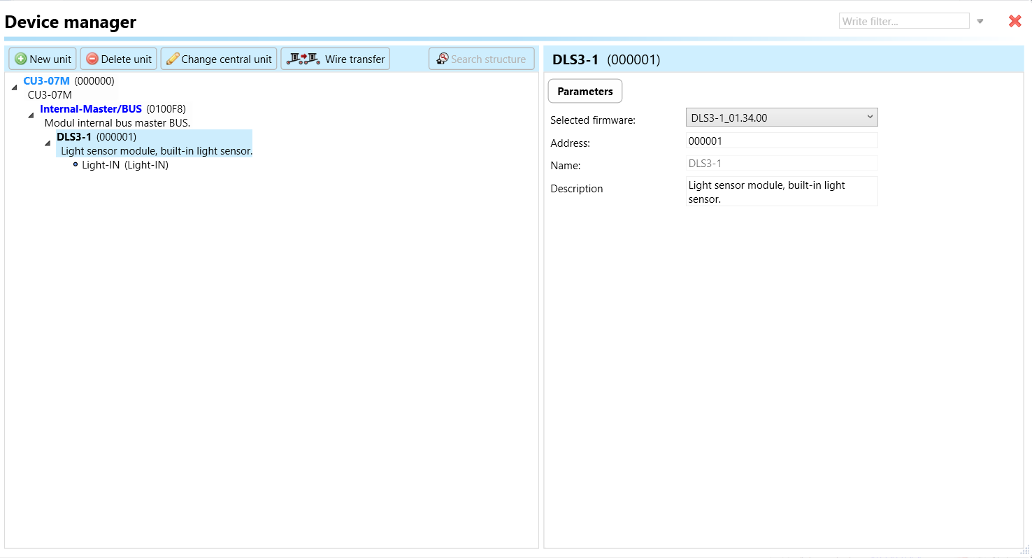
Clicking on the DLS3-1 (Fig.2), will navigate to selected firmware, unit address, name, and description, along with other parameters as described below :
It is important to add the device address for proper communication with the unit. The Hexadecimal device address can be find from the device.
LIght-IN: Light-IN refers to the input parameter that represents the incoming light intensity detected by the DLS3-01 luminescence sensor. This parameter provides real-time information about the light intensity at the sensor's location, allowing for dynamic adjustments in lighting control systems.

Average Time: Average Time parameter determines the time interval over which light intensity measurements are averaged. It influences the responsiveness and stability of the sensor's output by smoothing out short-term fluctuations.
Minimum Level: Minimum Level parameter sets the lower threshold for light intensity detection. It defines the minimum acceptable light intensity level that triggers sensor responses or actions.
Maximum Level: Maximum Level parameter defines the upper threshold for light intensity detection. It establishes the maximum acceptable light intensity level that triggers sensor responses or actions.
Exports for iNELS Cloud and APP
Setting Up Control and Monitoring for iNELS Cloud and iNELS App
It is possible to control and monitor all the bus units in iNELS cloud and iNELS app. There are two stages to set up this function. Stage one is to do configuration in iDM3 and stage 2 is to do Configuration in iNELS cloud page and iNELS app.
Configuration in iDM3.
1. Unit and Parameter Selection:
Begin by accessing the iDM3 interface on your PC connected to CU. Navigate to the Device Manager section and carefully select the units and parameters you wish to control. This step is essential for determining what gets exported to the iNELS cloud and app.

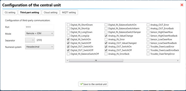
2. CU Configuration and Third-Party Settings
After the above step, go to the CU configuration in the iDM3, and select the page for third-party settings.
Inside the third-party settings page, designate the port for cloud connection. Set the mode of operation and choose the numerical system as hexadecimal. Pay close attention to verifying and configuring all essential parameters for successful cloud export.
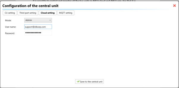
3. Cloud Settings:
Move on to the Cloud Settings section within iDM3.
Input the details of your iNELS cloud account. If you haven't created one, utilize the "New User" tab on the iNELS Cloud web page to establish a free account. (Inels Cloud - ElkoEP).
Select the mode and input the cloud account credentials. Save the project to the central unit to generate and store the export project file in the iNELS cloud account.
Configuration in iNELS cloud page and iNELS App.
1. Online Status Verification:
Once the cloud credentials and export settings in iDM3 are configured successfully, check the iNELS cloud account's Gateway section. Confirm that the Central Unit (CU) is online and that the export file has been automatically sent to the cloud under your account.
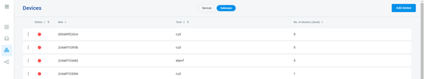
2. Device Creation in Cloud Platform:
In the cloud platform, you have to create new devices in order to control it remotely.
In the device tab, you will find the add device button, which can be used to associate export elements from IDM with the required types and icons.
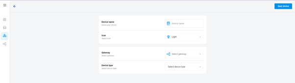
After entering any name of the device, you select the icon, the MAC address of the communication gateway (in this case CU3), a specific type of device and the address of a specific function and element from the iNELS BUS system.
In order to be able to use the iNELS application to control the devices from CU over the local network or the cloud, it is necessary to create a room for bus devices for each central unit and add the devices into the room.
Follow these steps meticulously to ensure a seamless configuration process for controlling and monitoring all bus units through iNELS cloud and iNELS app.
3rd Party Integration with iNELS BUS
3rd Party Integration (MQTT)
iNELS units support MQTT integration on central units CU3-07M, CU3-08M, CU3-09M, and CU3-10M. It is necessary to select the devices and parameters for 3rd party integration on the device manager in the iDM.
Please note that you have an MQTT broker (local or cloud) running in the installation for this integration.
After you have a working MQTT broker you need to configure iNELS Central units to communicate with it. If you have no knowledge of what MQTT is, you can learn about it from MQTT Essentials articles. https://www.hivemq.com/mqtt/
There is a pre-installed MQTT broker in the iNLES bridge, it can be used to connect the iNELS Central units for integration in your projects.
Configuration in iDM3: Select units of 3rd Party integration.
Unit and Parameter Selection:
Begin by accessing the iDM3 interface on your PC connected to CU. Navigate to the Device Manager section and carefully select the units and parameters you wish to control. This step is essential for determining what gets exported to the 3rd party integration via MQTT.

2. CU Configuration and Third-Party Settings
After the above step, go to the CU configuration in the iDM3, and select the page for third party settings.
Inside the third-party settings page, designate the port for third-party connection. Set the mode of operation and choose the numerical system as hexadecimal. Pay close attention to verifying and configuring all essential parameters for successful third-party integration.
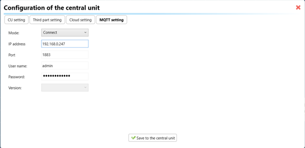
3. MQTT Settings:
Move on to the MQTT Settings section within iDM3.
Input the details of your MQTT broker.
Select the mode and input the broker credentials such as IP, port username and password. Save the project to the central unit.
MQTT payload
For MQTT payload description please refer the link below. https://wiki.inels.com/v/inels-bus/3rd-party-integration/mqtt-payload-description-of-inels-bus-devices
Appendices
Provide any optional, supplementary information that may help in providing a more comprehensive understanding of the product feature
Last updated