GSB3 XX/SX
Glass Switch Button with Symbol
GSB3-40/S, GSB3-60/S, GSB3-90/S
GSB3-240/S, GSB3-260/S, GSB3-290/S
Overview of devices
An overview of the product design and usage. Also includes circuit diagrams, terminal details, etc.,
The manual refers to the following glass switch buttons:
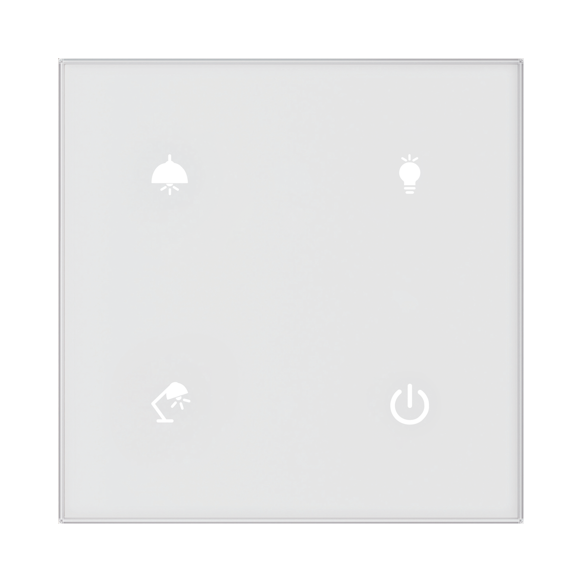
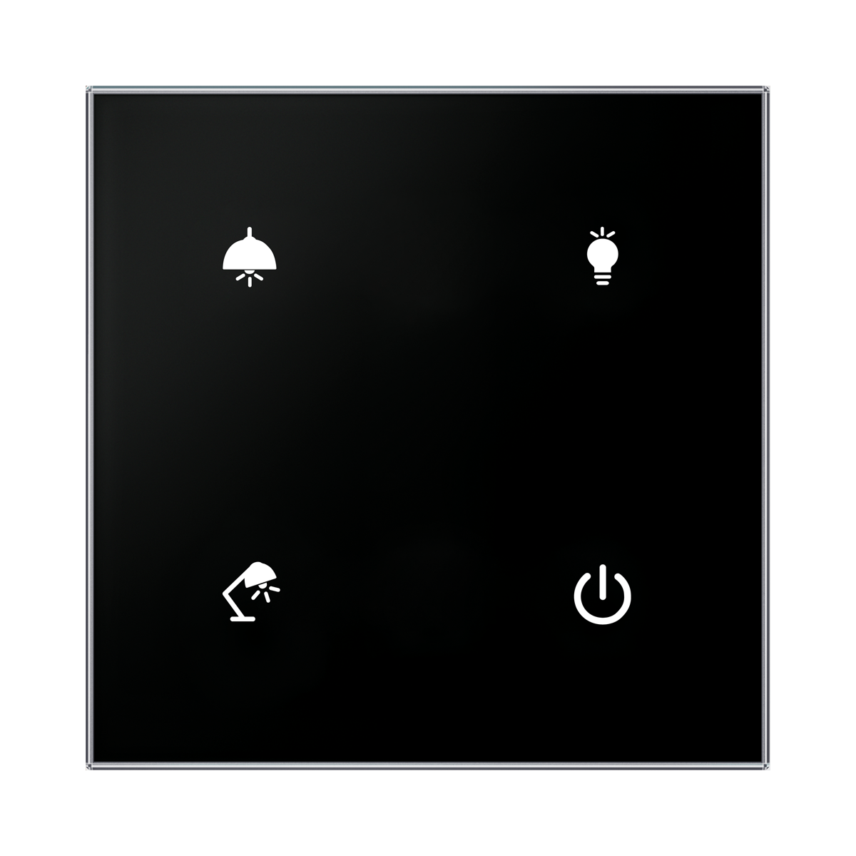
GSB3-40/S
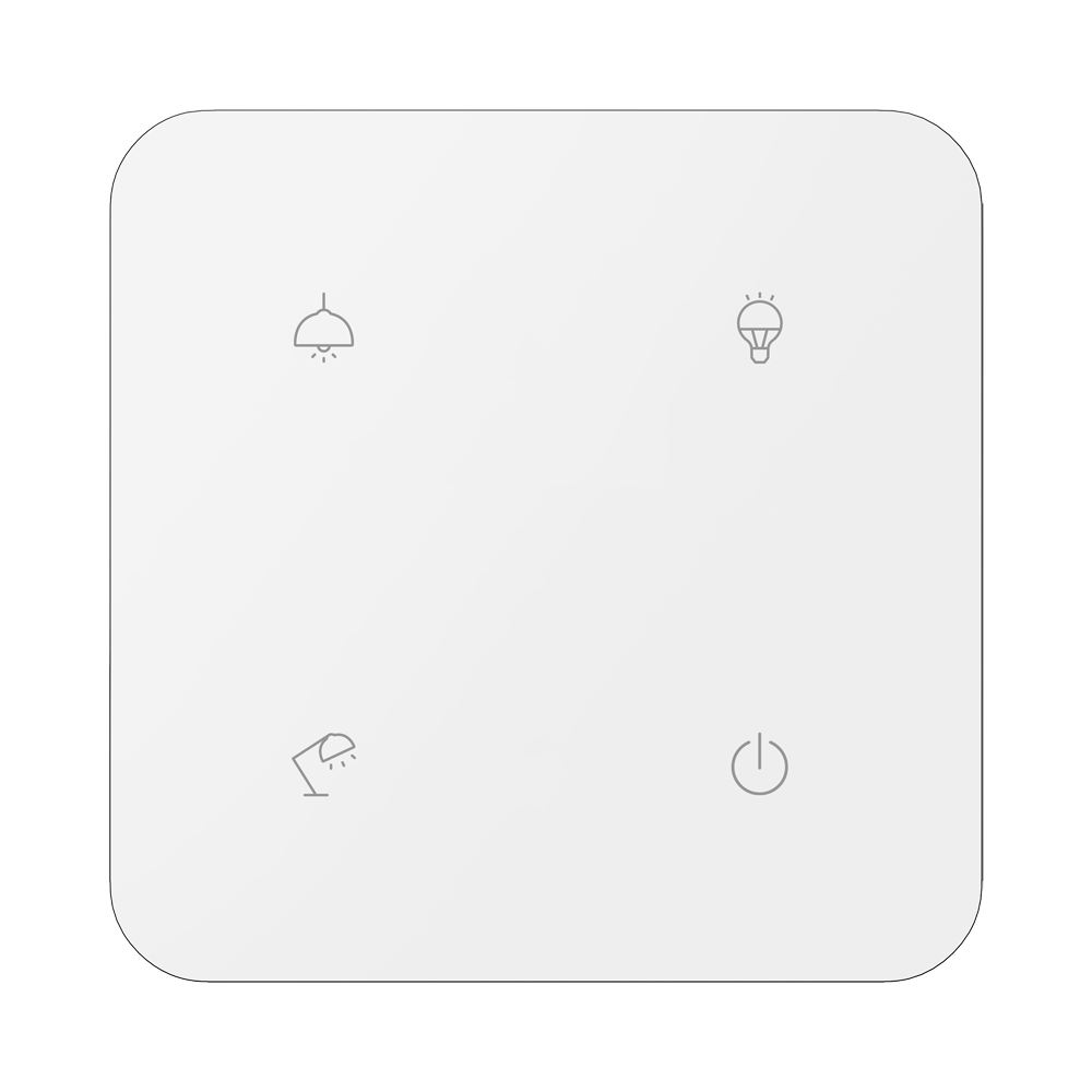
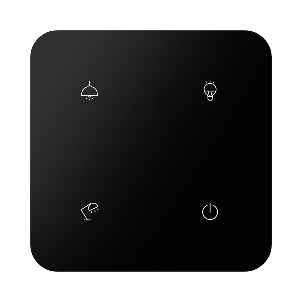
Wall-mounted glass touch controls, sharp, 4-button, built-in temperature sensor, 1x temperature input, 1x digital input.
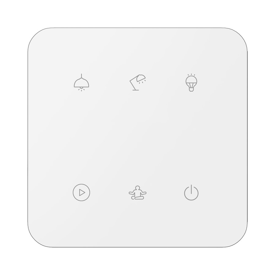
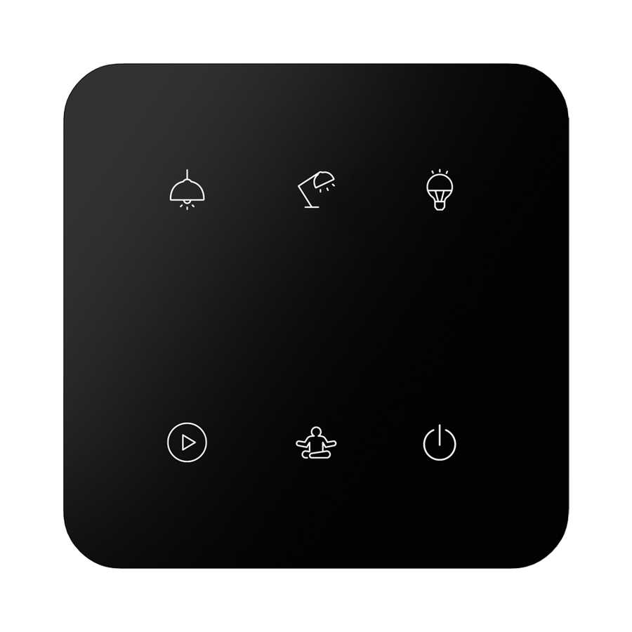
GSB3-60/S
Wall-mounted glass touch controls, sharp, 6-button, built-in temperature sensor, 1x temperature input, 1x digital input.
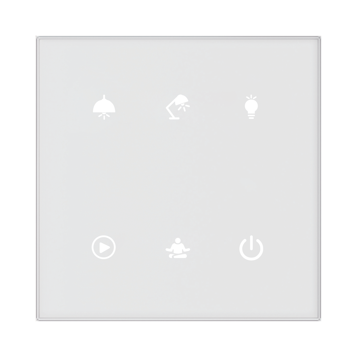
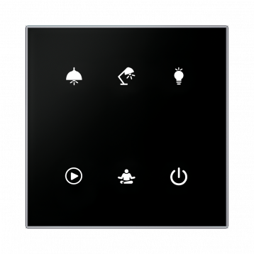
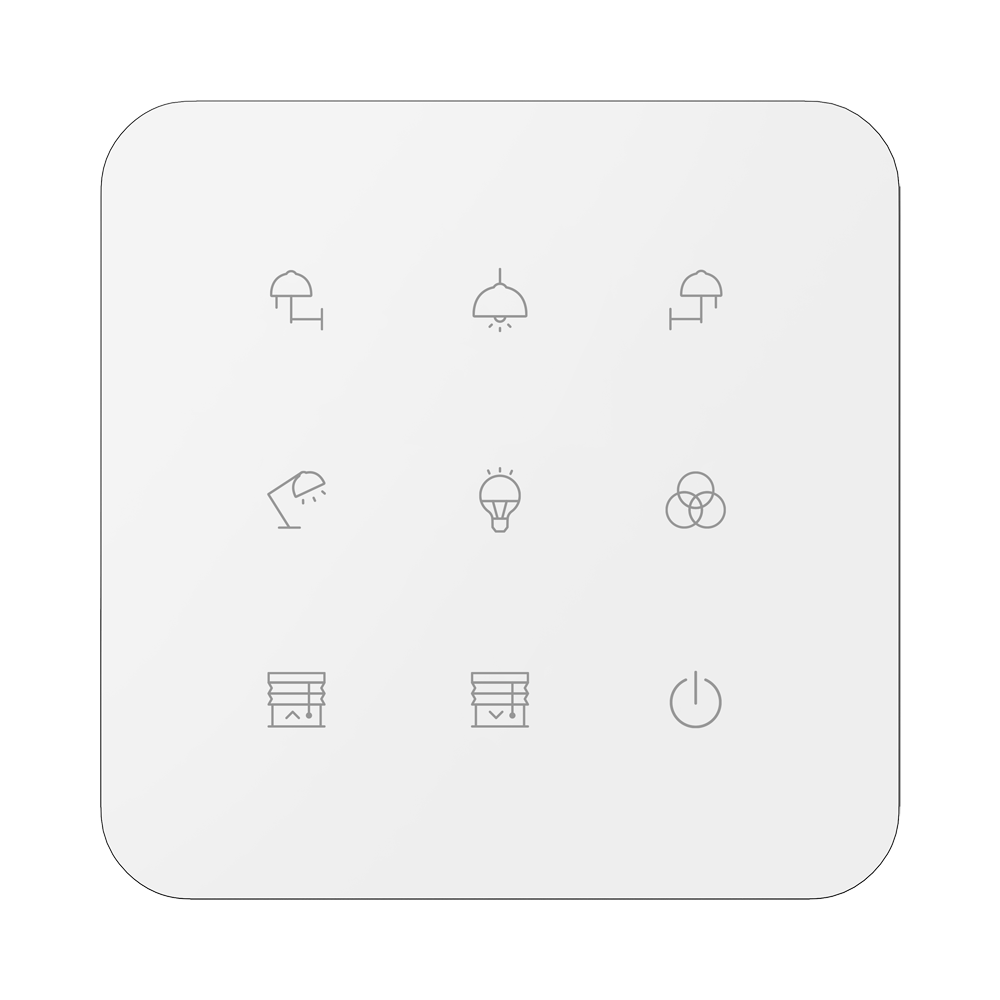
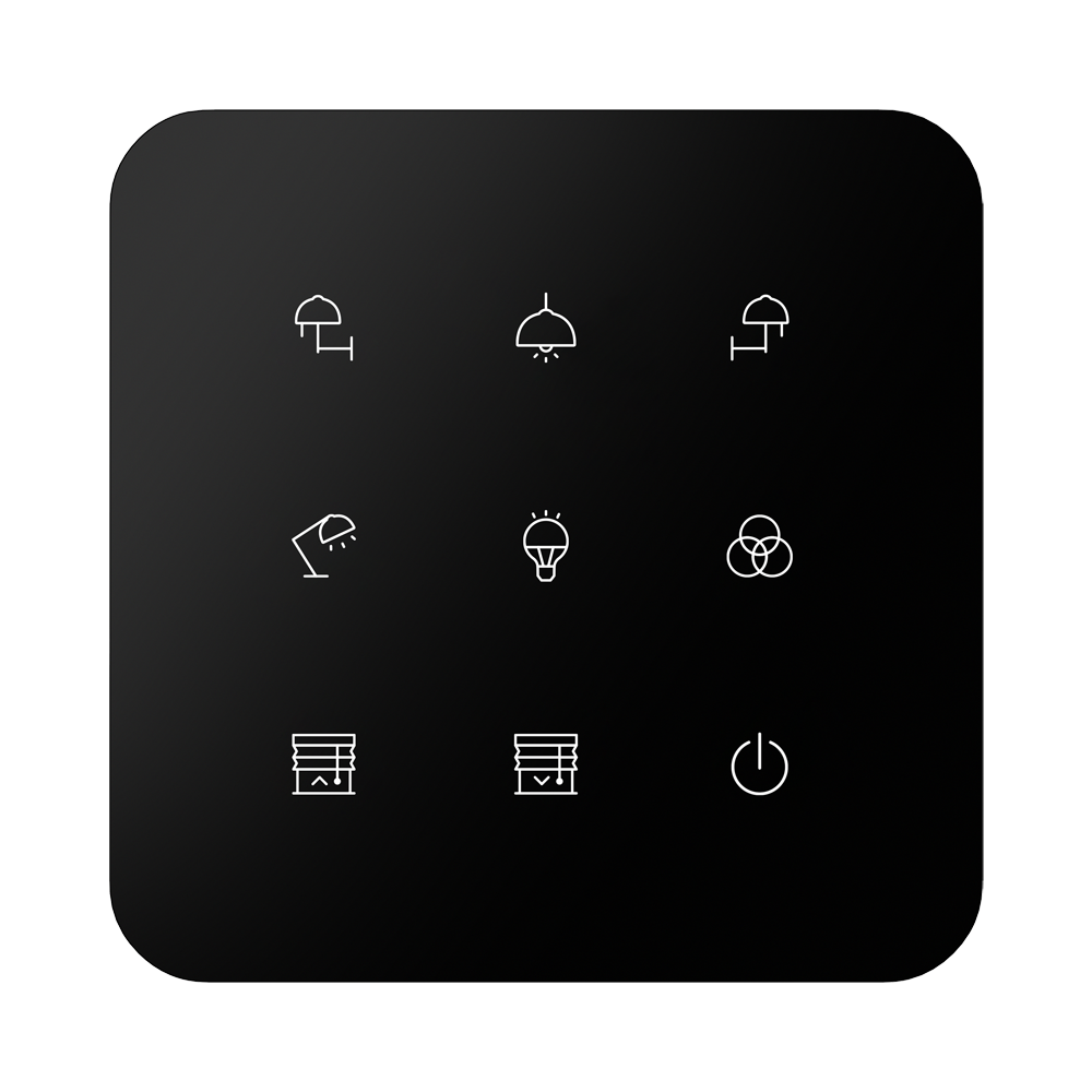
GSB3-90/S
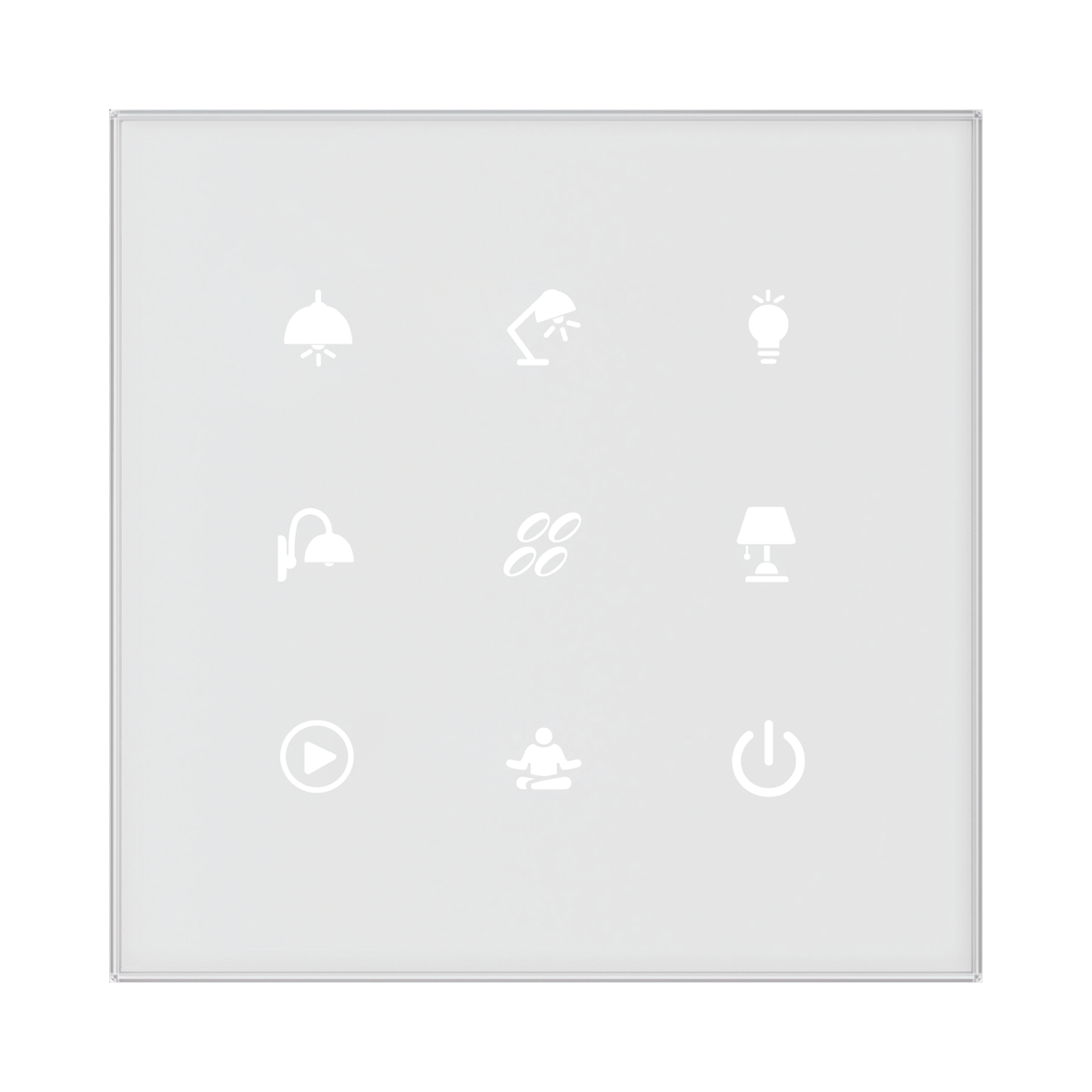
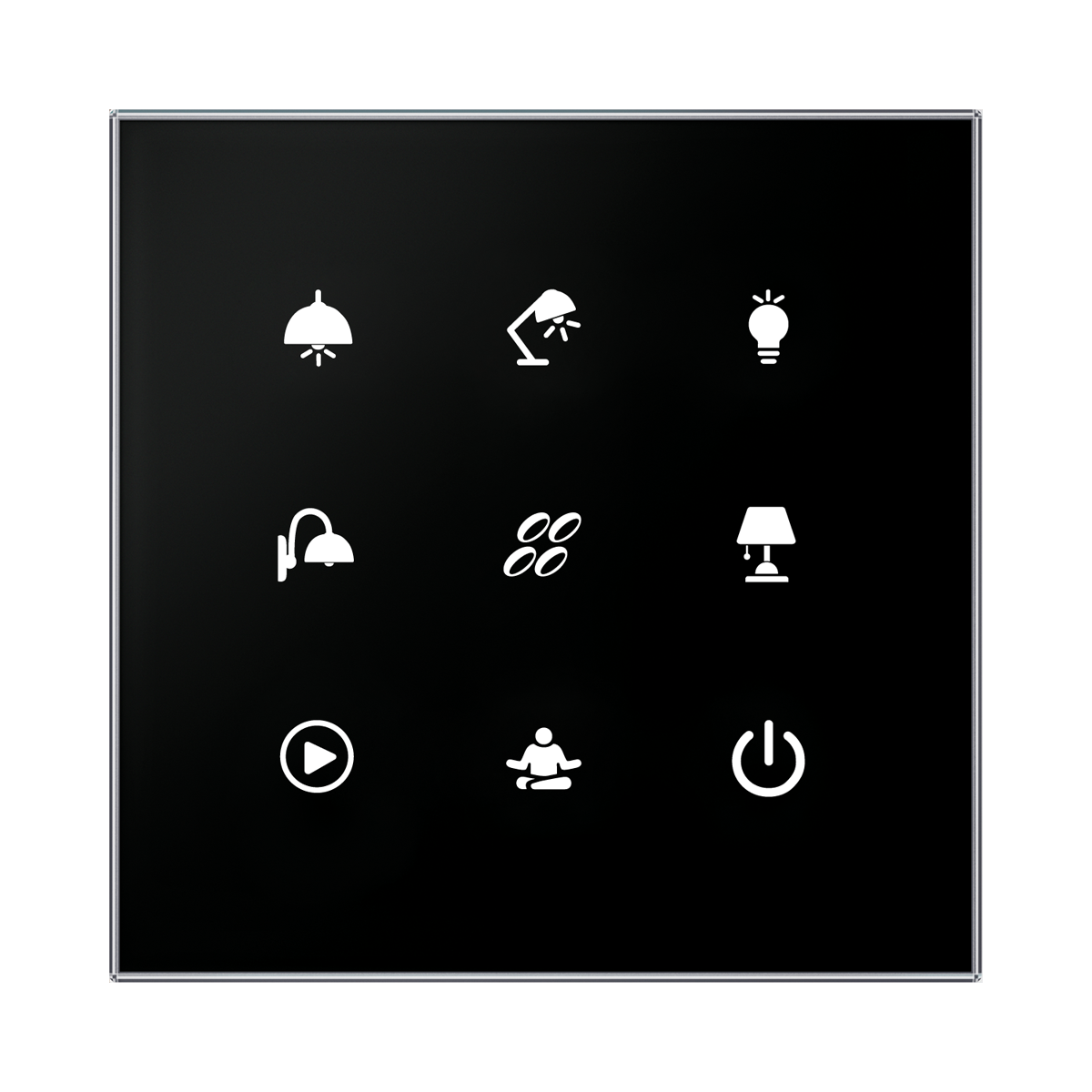
Wall-mounted glass touch controls, sharp, 9-button, built-in temperature sensor, 1x temperature input, 1x digital input.
GSB3-240/S
Wall-mounted glass touch controls, round, 4-button, built-in temperature sensor, 1x temperature input, 1x digital input.
GSB3-260/S
Wall-mounted glass touch controls, round, 6-button, built-in temperature sensor, 1x temperature input, 1x digital input.
.
GSB3-290/S
Wall-mounted glass touch controls, round, 9-button, built-in temperature sensor, 1x temperature input, 1x digital input.
Key Features
These glass touch controllers offer a range of features, customization options, and technological advantages for various applications, especially in guest room management systems and other projects within the iNELS system.
Design Variations:
- GSB3-40/S, GSB3-60/S, and GSB3-90/S models have a square design.
- GSB3-240/S, GSB3-260/S, and GSB3-290/S models have a round design.
Button Configuration:
- GSB3-40/S, GSB3-240/S: Four touch buttons
- GSB3-60/S, GSB3-260/S: Six touch buttons
- GSB3-90/S, GSB3-290/S: Nine touch buttons
- Button functions can be easily modified through software.
Engraving and Customization: Engraving of symbols is possible upon request. Each button can control any actuator (appliance) in the system.
Function Assignment: Each button can be assigned a different function or macro (set of functions). Allows control of several appliances simultaneously using a single button.
Glass Touch Panel: Design component of the iNELS system. Available in elegant black (GSB3-XXX/SB) and white (GSB3-XXX/SW) versions.
Illumination Options: Individual symbols can be illuminated in one of seven colors: red, green, blue, yellow, pink, turquoise, and white.
Standard Module Size and Mounting: All versions conform to the size of the standard module (94x94 mm). Designed for easy mounting into an installation box.
Additional Features in SBP/SWP Models: SBP/SWP versions are equipped with a proximity sensor. Proximity sensor can light up symbols by approaching the unit to approximately 0.25 m.
Integrated Temperature Sensor: Equipped with an integrated temperature sensor for monitoring and controlling room temperature.
Analog-to-Digital Input (AIN/DIN): Includes AIN/DIN for connecting potential-free contacts or external temperature sensors (TC/TZ). Enables measurement of external factors such as floor temperature.
Light Intensity Sensor (SWP/SBP Models): SWP/SBP models include a sensor for ambient light intensity. Uses light intensity information to switch the backlight of symbols and perform actions in the iDM3 software.
Advantages Over Conventional Switches/Buttons:
- Space-saving design.
- Signaling the state of any system output.
- Ability to measure temperature.
- Ability to connect external buttons or detectors.
Exemplary circuit diagram/ Wiring Diagram
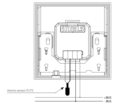
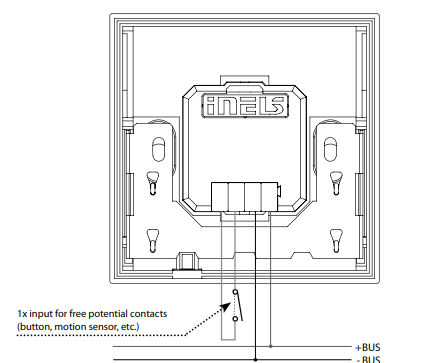
CONNECTION TO THE SYSTEM, INSTALLATION BUS
iNELS3 peripheral units are connected to the system through the BUS installation. Installation BUS conductors are connected to the terminal units to BUS+ and BUS- terminals, wires cannot be interchanged. For the installation of BUS, it is necessary to use a cable with a twisted pair of wires with a diameter of at least 0.8 mm, the recommended cable is iNELS BUS Cable, whose features best meet the requirements of the BUS installation. Bearing in mind that in terms of all the properties, it is possible in most cases to also use the cable JYSTY 1x2x0.8 or JYSTY 2x2x0.8, however, it is not recommended as the best option. With a cable with two pairs of twisted wires, it is not possible to use the second pair of the other for modulated signal due to the speed of communications; it is not possible within one cable to use one pair for one segment BUS and the second pair for the second segment BUS. For the installation of BUS, it is vital to ensure that it is kept at a distance from the power lines of at least 30 cm and must be installed in accordance with its mechanical properties. To increase the mechanical resistance of cables we recommend installation into a conduit of suitable diameter. BUS topology installation is free except for the ring, wherein each end of the bus must terminate at the terminals BUS + and BUS- peripheral unit. While maintaining all the above requirements, the maximum length of one segment of the installation BUS can reach up to 300 m. Due to the data communication and supply of units in one pair of wires, it is necessary to keep in mind the diameter of wires regarding voltage loss on the lead and the maximum current drawn. The maximum length of the BUS applies, provided that it complies with the tolerance of the supply voltage.
CAPACITY AND CENTRAL UNIT
It is possible to connect to the central unit CU3-01M/02M or miniCU CU3-07/08/09/10M independent BUSes by means of terminals BUS1+, BUS1- or BUS2+, BUS2-. It is possible to connect to each BUS up to 32 units, so it is possible to connect directly to the central unit a total of 64 units. It is necessary to comply with the requirement of a maximum load of one BUS line - a maximum of up to 1000 mA current. When connecting units that draw greater than 1A, BPS3-01M with 3A sampling can be used. It is the sum of the rated currents of the units connected to the BUS line, other units can be connected using the units MI3-02M (for CU3-01M/02M), which generate further BUSes. These are connected to the CU3-01M/02M unit via the system BUS EBM and you can connect 8 units via EBM BUS to the central unit MI3-02M.
SUPPLYING THE SYSTEM
For supplying power to system units, it is recommended to use the power source of ELKO EP titled PSM3-30/iNELS, PSM3-60/iNELS, PSM3-100/iNELS or PS3-30/iNELS. We recommend backing up the system with backup batteries.
GENERAL INFORMATION
To operate the unit, it is necessary that the unit is connected to a central unit CU3 series, connected to the central unit of the system CU3, or to a system that already contains this unit as its expansion to include further systems. All unit parameters are set through the central unit CU3-0XM in the software iDM3. There is an LED diode on the PCB for indication of supply voltage and communication with the central unit series CU3. In case the RUN diode flashes at regular intervals, so there is standard communication between the unit and BUS. If the RUN diode lights permanently, the unit is supplied from BUS, but there is no communication between BUS and the unit. If the RUN diode is OFF, there is no supply voltage on the terminals BUS+ and BUS-
Compatibility chart ( CU, minimal FW version and Integration)
The chart illustrates the compatibility between glass switchboards and various central units, firmware versions, and integration options.
The chart shows the Firmware for GSB3-40/S, GSB3-60/S, GSB3-90/S
1
CU3-01M
Preparation
NA
NA
2
CU3-02M
Preparation
NA
NA
3
CU3-07M
Preparation
Yes
Yes
4
CU3-08M
Preparation
Yes
Yes
6
CU3-09M
Preparation
Preparation
Preparation
7
CU3-10M
Preparation
Preparation
Preparation
Programming in iDM(Parameters, Functions and Logic)
Introduction
iNELS Design Manager, or IDM3, is for programming iNELS units. This software serves as the platform for configuring device parameters, defining functions, and executing the programming required for iNELS units.
Device parameters, such as sensor range and thresholds, backlights, and operational modes, can be easily adjusted within the IDM3.
The process of programming in IDM3 typically involves defining functions and establishing logical connections between different devices. This allows for the creation of automation scenarios and the implementation of intelligent control strategies.
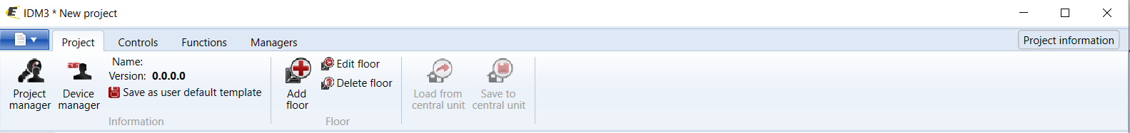
Starting up
Select the "blue control icon" as shown in Fig 1 > Clicking on the option "New project from default template“ allows you to create a new project from a predefined template.
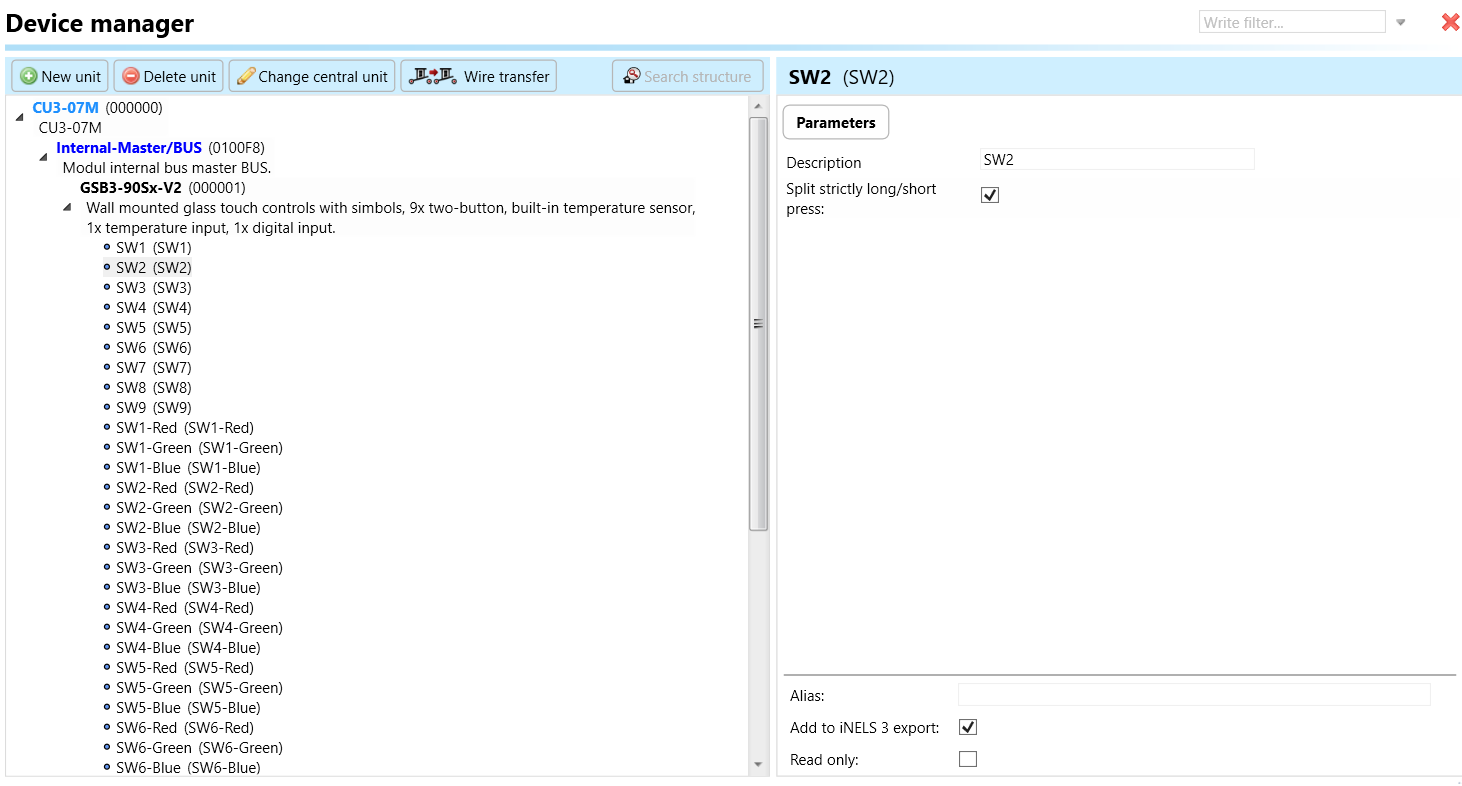
Select the "Device manager" (Fig 1)> Add "New unit "> Select the central unit > Add "New unit">Select the "Internal-Master/ BUS"> Add "New unit "> Add the devices> Click on the devices to see the "Parameters".
Parameters
Parameters in the iNELS devices refer to the measurable factors or characteristics that define the behavior or performance of the device. These could include electrical properties, physical dimensions, environmental conditions, and various other specifications depending on the type of device.
These are settings specific to individual devices within your automation system. The specific parameters of the GSB3 (Symbol) in the iDM as shown in Fig.2
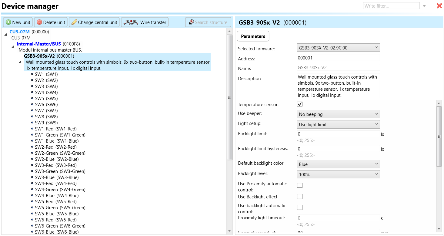
Clicking on the GSB3-90Sx-V2(Fig.2), will navigate to the selected firmware, unit address, name, and description, along with other parameters as described below :
It is important to add the device address for proper communication with the unit. The Hexadecimal device address can be find from the device.
Temperature sensor: The temperature sensor integrated into the metal switch buttons allows temperature measurement within the environment where the switches are installed. This sensor provides data on ambient temperature, enabling users to monitor and potentially control environmental conditions based on temperature readings.
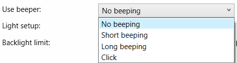
Use beeper: The "beeper" is used to emit a beeping sound to alert or notify users of a particular event or condition (Fig.2 and Fig.3 ).
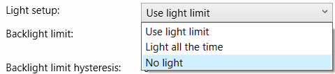
Light setup: To use the light upon preference by the user (Fig.2 and Fig.4).
Backlight limit: A "backlight limit" is a parameter that sets the maximum or minimum brightness of the backlight based on certain conditions or user preferences. "backlight" refers to the illumination of a display from behind, often in devices like LCD screens. The backlight is responsible for making the display visible.
Backlight limit hysteresis: Hysteresis generally refers to the dependence of a system not only on its current environment but also on its past environment. In automation, hysteresis is often used to prevent rapid or unnecessary switching of devices.
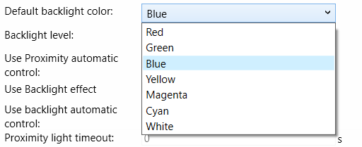
Default backlight color: It is a customizable setting, allowing users to choose their preferred backlight color as shown in Fig: 5 of the buttons when it is in the default state.
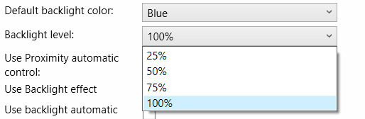
Backlight level: The backlight level refers to the intensity or brightness of the backlight used to illuminate the display. Adjusting the backlight level as shown in Fig: 6 allows users to control the amount of light emitted by the display
Use Proximity automatic control: Proximity automatic control refers to a system that adjusts or triggers actions based on the proximity of an object or person. For example: In our smart home systems, lights or appliances can be set to turn on or off automatically when a person enters or leaves a room.
Use Backlight effect: The backlight effect can refer to different visual enhancements or features related to the lighting of a display. Example: The glass switch button comes with customizable backlight effects. Users can choose from a variety of backlight colors and effects to create an immersive experience.
Use Backlight automatic control: Backlight automatic control involves the automatic adjustment of the backlight intensity on a display based on certain conditions. The key benefit of backlight automatic control is to optimize the display brightness according to the surrounding conditions, providing a more comfortable and efficient user experience. This technology is particularly useful in portable devices where battery life is a critical consideration, as it helps strike a balance between visibility and energy conservation without requiring manual adjustments from the user.
Proximity Light timeout: Proximity light timeout refers to a setting or feature that controls how long the display backlight remains active when the device is in use and detects proximity to an object or person.
Proximity sensitivity: Proximity sensitivity refers to the level of responsiveness or reactivity of a proximity sensor. Proximity sensors are devices that detect the presence or absence of an object within a certain range without any physical contact.
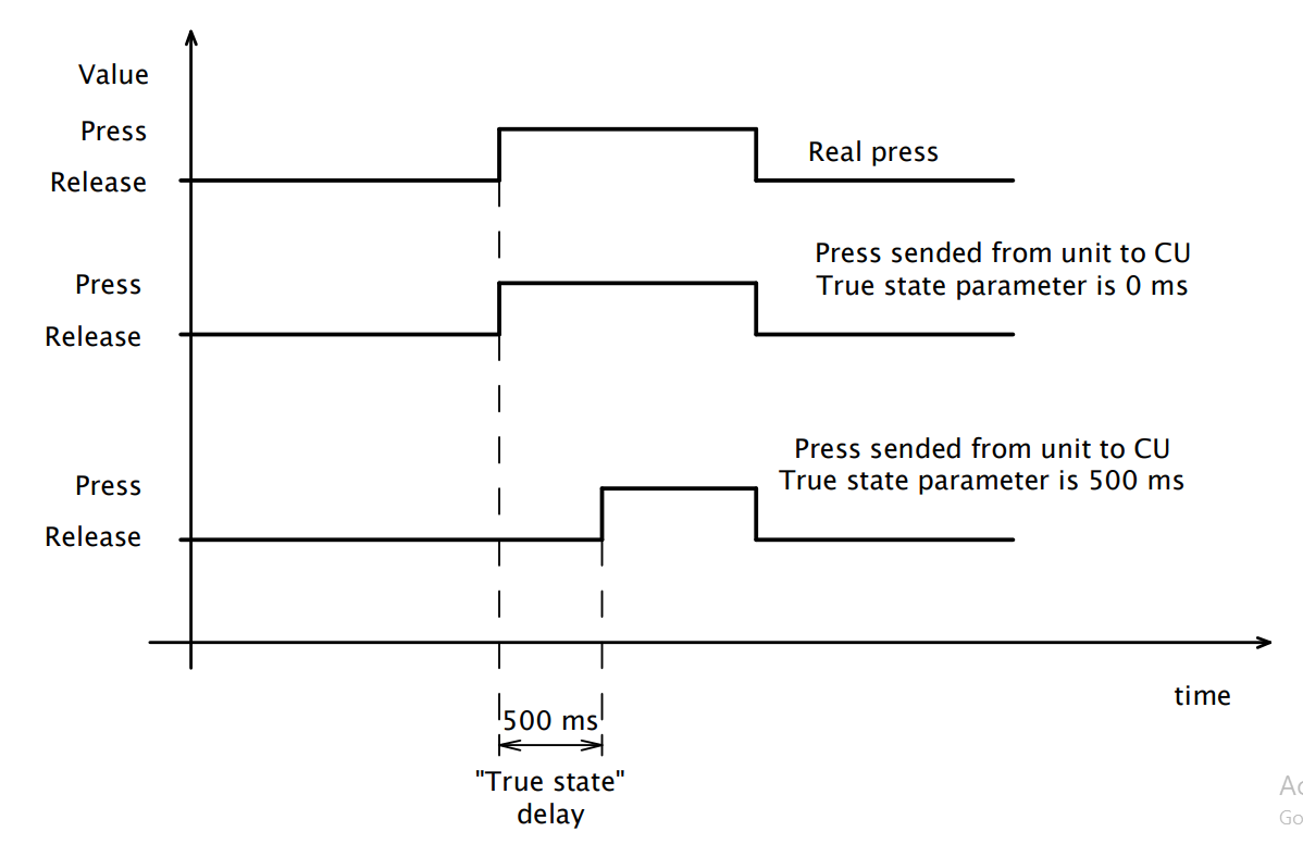
True state button: True state is a crucial parameter designed to address issues related to false button presses caused by interference in your system. When configured, this parameter dictates the signaling delay to the Central Unit (CU) once the button is pressed. This delay serves as a protective measure against erroneous inputs—specifically, if a false press occurs within a duration shorter than the time specified in the True State parameter, the information will not be transmitted to the CU. Consequently, the unit will intelligently disregard such short-lived signals, ensuring that only valid button presses are acknowledged and acted upon. This feature enhances the reliability and accuracy of your system, especially in environments prone to interference, offering a more robust and secure user experience.
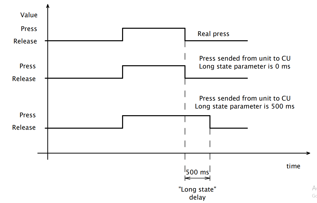
Long state button: Long State plays a pivotal role in mitigating challenges associated with BUS interference and slow communication in your system. Specifically, this parameter sets the signaling delay to the Central Unit (CU) when a button is released. In installations where BUS communication faces sluggishness due to interference, the Long State parameter proves invaluable.In scenarios where a button press is short and the BUS communication is slow, there might be a risk of the unit not being able to transmit the information to the CU in a timely manner, especially regarding the acknowledgment of a press and subsequent release event. To address this concern, the Long State parameter comes into play. It extends the press time by the specified value, allowing the unit to compensate for the sluggish BUS communication. This ensures that the CU receives the necessary information regarding the button press and subsequent release, even in situations where the standard communication speed may be compromised. As a result, Long State contributes to the reliability and responsiveness of your system, offering a solution tailored to environments with BUS-related challenges.
Use Button SW1-SW9: This parameter allows users to specify the functionality or action assigned to each of the nine touch buttons (SW 1 through SW 9) on the GSB3 glass touch controller.
Functionality: Users can customize the behavior of each button according to their requirements, assigning specific tasks, functions, or macros to individual buttons.
Configuration: Through the device's software interface, users can define the action or function associated with each button, such as turning on/off lights, adjusting temperature, activating scenes, or controlling other appliances within the system.
SW1-SW9:
A "switch" could refer to a virtual or physical switch that controls a specific function within the GSB3-XX/SX. For example, you might have switches to control lights, heating, or other smart devices in your installation. These switches can be programmed and configured within the iNELS Design Manager to customize the behaviour of your system.
The set of actions in SW “ short press, short release, long press, long release, and permanent action can be used with various functions.
2. SW1-SW9 (Red, Green, Blue): A "switch" refers to a virtual or physical switch that controls a specific function within the GSB3-XX/SX. For example, these switches can control lights especially red, green, and blue.
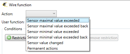
3. Inter-Therm: The feature that allows you to configure or monitor the temperature data from the internal temperature sensor in the GSB3. You can use this information to automate climate control, adjust heating or cooling systems, or trigger alerts based on temperature thresholds.
The set of actions “Sensor maximal value exceeded, Sensor maximal value exceeded back, Sensor minimal value exceed, Sensor minimal value exceed back, Sensor value change and permanent action can be use with various functions.
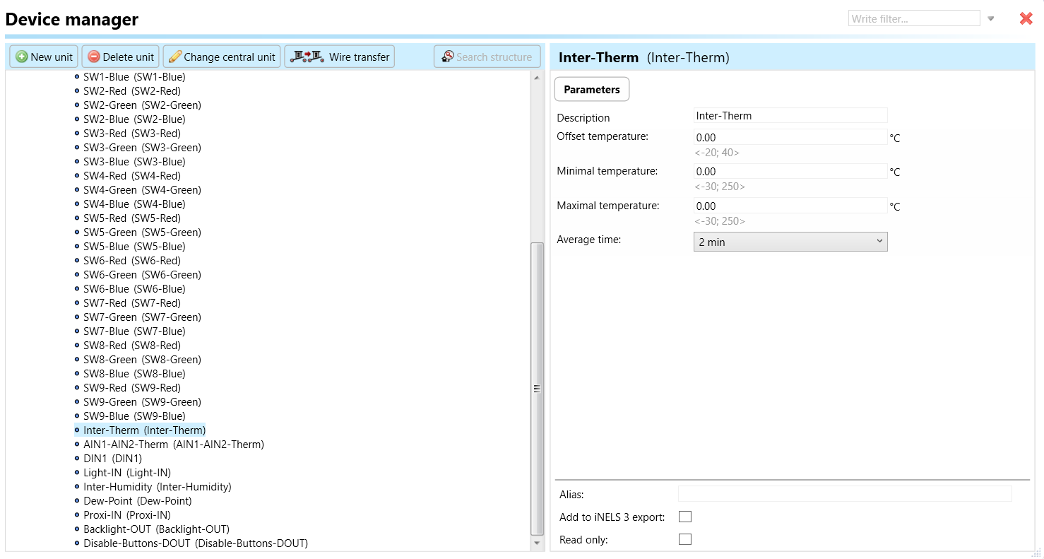
Offset Temperature: Offset temperature refers to a user-configurable adjustment applied to the temperature readings from the connected sensor. It allows users to compensate for any systematic errors or inaccuracies in the temperature measurements. The offset temperature parameter enables fine-tuning of the temperature readings to improve accuracy and alignment with reference values.
Minimal Temperature: The minimal temperature parameter indicates the lowest temperature that the temperature sensor is capable of measuring accurately within its specified operating range. This value is crucial for ensuring that the sensor can detect and report temperatures accurately, especially in environments where temperatures may drop to lower levels.
Maximal Temperature: Conversely, the maximal temperature parameter indicates the highest temperature that the temperature sensor is capable of measuring accurately within its specified operating range. This value is essential for ensuring that the sensor can withstand high temperatures without damage and accurately report temperature readings in environments with elevated temperatures.
Average Time: Average time refers to the duration over which temperature measurements are averaged to calculate a representative temperature value. This parameter is relevant in scenarios where temperature fluctuations occur rapidly, and averaging measurements over time helps smooth out variations to provide a more stable and accurate temperature reading.
AIN1-AIN2 Therm: An analog input for temperature typically refers to a feature in a GSB3 device that can accept and process analog signals from temperature sensors. Analog signals in this context represent a continuous range of values that correspond to temperature variations. For example, a temperature sensor might output an analog voltage or current signal that changes proportionally with the temperature it's measuring. The analog input signals are converted into temperature readings. This feature allows for more precise control or monitoring of temperature within a system. It's commonly used in situations where a high level of accuracy is required for temperature-sensitive applications, such as climate control.
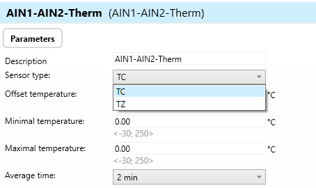
Sensor Type: This parameter defines the type of temperature sensor connected to the AIN1- AIN2- Therm input. It specifies the types of temperature sensors, such as TC/TZ . The sensor type parameter ensures compatibility between the connected sensor and the device, allowing accurate temperature measurement.
Please refer the other parameters from Inter-Therm
5. DIN1: Digital input typically refers to a feature in a GSB3 device that can accept and process binary signals, where the signal is either high (1) or low (0). Digital inputs can be used to receive signals from various sensors or devices that provide binary information. For example, a digital input could be used to connect a motion sensor or a door/window sensor. When motion is detected or a door is opened, the sensor sends a digital signal (1), and when there's no motion or the door is closed, it sends a different digital signal (0). iNELS Design Manager configures actions or responses based on the state of these digital inputs. For instance, you could set up automation rules to turn on lights when motion is detected (digital input goes to 1) or send an alert when a door is opened (digital input goes to 1).
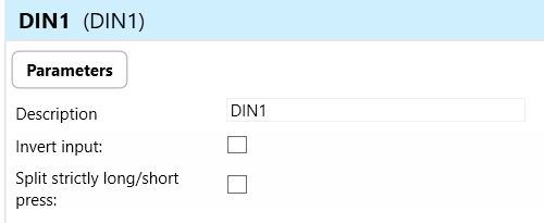
Invert Input: "Invert input" refers to a feature that allows users to invert or reverse the logic of the digital input signal received by the GSB3 device. In other words, when the invert input feature is enabled, a logic HIGH signal (e.g., 1 or ON) at the input would be interpreted as a logic LOW signal (e.g., 0 or OFF), and vice versa.
Purpose: This feature provides flexibility in configuring the behavior of the digital input signal. It can be useful in scenarios where the external device or sensor connected to the MSB3 operates with an inverted logic compared to the default interpretation of the GSB3 device.
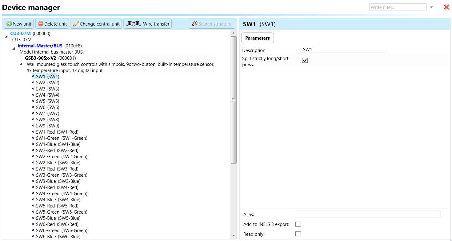
Split Strictly Long/Short Press: "Split strictly long/short press" refers to a feature that distinguishes between long and short press actions on the digital input of the GSB3 device.
Long Press: Holding the digital input signal for a predefined duration (longer than a specified threshold) before releasing it triggers a long press action.
Short Press: Briefly activating the digital input signal without holding it for the predefined duration triggers a short press action.
Purpose: This feature allows users to assign different actions or functions to short and long press events on the digital input. It enhances usability and control flexibility by providing distinct functionalities for different durations of input activation
6. Light-IN: refers to the luminance sensor which involves the integration with lighting control systems and uses the sensor's readings to dynamically control artificial lighting sources.
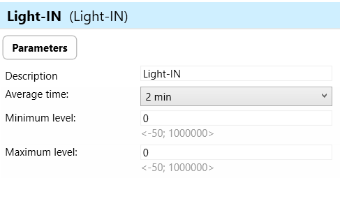
Average Time: Average time refers to the duration over which the luminance sensor averages multiple readings to calculate luminance value. This parameter helps to smooth out fluctuations in light levels caused by factors such as changes in natural light, flickering, or sensor noise.
Minimum Level: Minimum level refers to the lowest luminance threshold at which the GSB3 device will activate or adjust artificial lighting sources in response to changes in light levels detected by the luminance sensor. When the measured luminance falls below the minimum level, the GSB3 device initiates appropriate actions to increase the brightness of artificial lighting sources.
Maximum Level: Maximum level refers to the highest luminance threshold at which the GSB3 device will deactivate or adjust artificial lighting sources in response to changes in light levels detected by the luminance sensor. When the measured luminance exceeds the maximum level, the MSB3 device initiates appropriate actions to decrease the brightness of artificial lighting sources.
7. Inter-Humidity: The internal humidity sensor is a component within the GSB3 device that measures the moisture content in the surrounding environment. This sensor provides data on humidity levels, allowing the system to make informed decisions or trigger actions based on those readings. For example, if the internal humidity sensor detects high humidity levels, the system may trigger ventilation or air conditioning to maintain a comfortable environment. Set up rules or automation scenarios based on the readings from the internal humidity sensor.
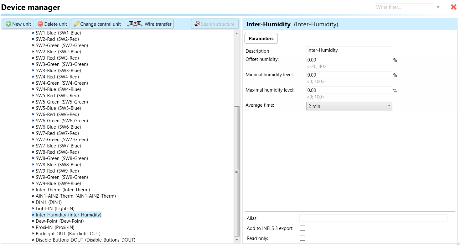
Offset Humidity: Offset humidity refers to an adjustment applied to the measured humidity value to account for any discrepancies or inaccuracies in the sensor readings. It allows users to calibrate the humidity readings to ensure accuracy.
Minimal Humidity Level: Minimal humidity level denotes the lowest acceptable humidity threshold in the environment being monitored. Users can set a minimum humidity level to trigger alerts or actions if the humidity falls below this threshold.
Maximal Humidity Level: Maximal humidity level indicates the highest acceptable humidity threshold in the monitored environment. Users can set a maximum humidity level to trigger alerts or actions if the humidity exceeds this threshold.
Average Time: Average time refers to the duration over which the device calculates the average humidity value.Users can specify the time interval over which the device computes the average humidity, which can provide a more stable and accurate representation of the environmental conditions.
8. Dew-Point: The dew point is the temperature at which air becomes saturated with moisture and dew or frost begins to form. It's the point at which the air holds the maximum amount of water vapor it can, and any further cooling will result in the condensation of water vapor into liquid water or frost. In climate control system, monitoring the dew point can be important for maintaining a comfortable indoor environment and preventing issues like condensation on windows or roof surfaces.
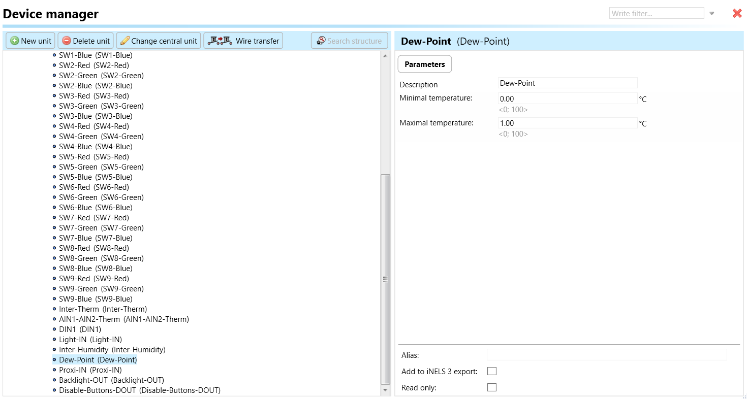
Minimal Temperature: Minimal temperature refers to the lowest acceptable temperature threshold in the environment being monitored.
Maximal Temperature: Maximal temperature indicates the highest acceptable temperature threshold in the monitored environment.
9. Proxi IN: Input for proximity sensor depends on the input it will give action to trigger the backlights or any other functions
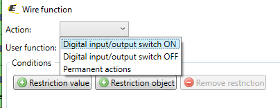
10. Backlight-OUT: Refers to the element related to the backlighting of all point-illuminated LED in buttons/switches on GSB3 devices. The set of actions “Digital input/output switch ON, “Digital input/output switch OFF and permanent action can be used with various functions.
11. Disable-Buttons-DOUT: This parameter is used for disabling buttons, preventing those buttons from triggering specific actions or functions within a system. The set of actions “Digital input/output switch ON, “Digital input/output switch OFF and permanent action can be used with various functions.
Exports for iNELS Cloud and APP
Setting Up Control and Monitoring for iNELS Cloud and iNELS App
It is possible to control and monitor all the bus units in iNELS cloud and iNELS app. There are two stages to setup this function. Stage one is to do configuration in iDM3 and stage 2 is to do Configuration in iNELS cloud page and iNELS app.
Configuration in iDM3.
1. Unit and Parameter Selection:
Begin by accessing the iDM3 interface on your PC connected to CU. Navigate to the Device Manager section and carefully select the units and parameters you wish to control. This step is essential for determining what gets exported to the iNELS cloud and app.
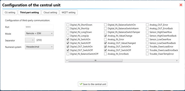
2. CU Configuration and Third-Party Settings :
After the above step, go to the CU configuration in the iDM3, and select the page for third party settings.
Inside the third-party settings page, designate the port for cloud connection. Set the mode of operation and choose the numerical system as hexadecimal. Pay close attention to verifying and configuring all essential parameters for successful cloud export.
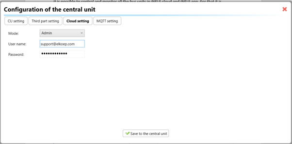
3. Cloud Settings:
Move on to the Cloud Settings section within iDM3.
Input the details of your iNELS cloud account. If you haven't created one, utilize the "New User" tab on the iNELS Cloud web page to establish a free account. (Inels Cloud - ElkoEP).
Select the mode and input the cloud account credentials. Save the project to the central unit to generate and store the export project file in the iNELS cloud account.
Configuration in iNELS cloud page and iNELS App.
1. Online Status Verification:
Once the cloud credentials and export settings in iDM3 are configured successfully, check the iNELS cloud account's Gateway section. Confirm that the Central Unit (CU) is online and that the export file has been automatically sent to the cloud under your account.
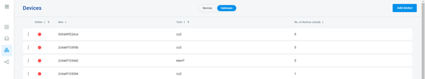
2. Device Creation in Cloud Platform:
In the cloud platform, you have to create new devices in order to control it remotely.
In the device tab, you will find the add device button, which can be used to associate export elements from IDM with the required types and icons.
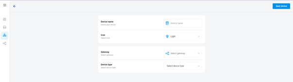
After entering any name of the device, you select the icon, the MAC address of the communication gateway (in this case CU3), a specific type of device and the address of a specific function and element from the iNELS BUS system.
In order to be able to use the iNELS application to control the devices from CU over the local network or the cloud, it is necessary to create a room for bus devices for each central unit and add the devices into the room.
Follow these steps meticulously to ensure a seamless configuration process for controlling and monitoring all bus units through iNELS cloud and iNELS app.
3rd Party Integration with iNELS BUS
3rd Party Integration (MQTT)
iNELS units support MQTT integration on central units CU3-07M, CU3-08M, CU3-09M, and CU3-10M. It is necessary to select the devices and parameters for 3rd party integration on the device manager in the iDM.
Please note that you have an MQTT broker (local or cloud) running in the installation for this integration.
After you have a working MQTT broker you need to configure iNELS Central units to communicate with it. If you have no knowledge of what MQTT is, you can learn about it from MQTT Essentials articles. https://www.hivemq.com/mqtt/
There is a pre-installed MQTT broker in the iNLES bridge, it can be used to connect the iNELS Central units for integration in your projects.
Configuration in iDM3: Select units of 3rd Party integration.
Unit and Parameter Selection:
Begin by accessing the iDM3 interface on your PC connected to CU. Navigate to the Device Manager section and carefully select the units and parameters you wish to control. This step is essential for determining what gets exported to the 3rd party integration via MQTT.
2. CU Configuration and Third-Party Settings :
After the above step, go to the CU configuration in the iDM3, and select the page for third party settings.
Inside the third-party settings page, designate the port for third-party connection. Set the mode of operation and choose the numerical system as hexadecimal. Pay close attention to verifying and configuring all essential parameters for successful third-party integration.
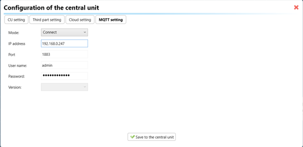
3. MQTT Settings:
Move on to the MQTT Settings section within iDM3.
Input the details of your MQTT broker.
Select the mode and input the broker credentials such as IP, port username and password. Save the project to the central unit.
MQTT payload
For MQTT payload description please refer the link below. https://wiki.inels.com/v/inels-bus/3rd-party-integration/mqtt-payload-description-of-inels-bus-devices
Appendices
Last updated