> For the complete documentation index, see [llms.txt](https://wiki.inels.com/llms.txt). Markdown versions of documentation pages are available by appending `.md` to page URLs; this page is available as [Markdown](https://wiki.inels.com/inels-bus/inspinia/inels-integration-to-skyplatform/inels-wireless-on-sky-platform.md).
# INELS WIRELESS on Sky Platform
## Introduction
The integration of **iNELS Wireless** into **SkyPlatform** brings a unified, scalable, and user-friendly solution for both residential and commercial projects. With this update, system integrators can now configure, monitor, and control iNELS Wireless devices directly through **Inspinia Touch Screens** and centralized servers, ensuring smooth operation across single rooms or entire facilities.
This solution is designed for:
* **System integrators** – needing fast, scalable deployment and flexible project expansion.
* **End-users** – who benefit from intuitive control via Inspinia touch screens, mobile apps, and cloud access.
## System Units (Gateways)
System units are divided into **two groups**, each serving different types of iNELS Wireless components.
### A) iNELS Wireless
Gateways communicate using **iNELS RFIO and RFIO2 protocols** for **bidirectional communication** with devices. They connect to a router via LAN or Wi-Fi. Supported devices include:
* **eLAN-RF-103**
* **eLAN-RF-204**
* **RFTC-3**
### B) iNELS Home
The gateway communicates using the **iNELS RFIO3 protocol** for **bidirectional communication** with devices. It connects to a router via Wi-Fi. Supported device:
* **Mini Bridge (MB-1)**
## How to use it on Sky Platform?
First step with Sky Platform, from creating an account to creating a project are explained **here**. It is essential to read and learn it prior to continue next step. If you're ready to continue, let's jump on the subject right away:
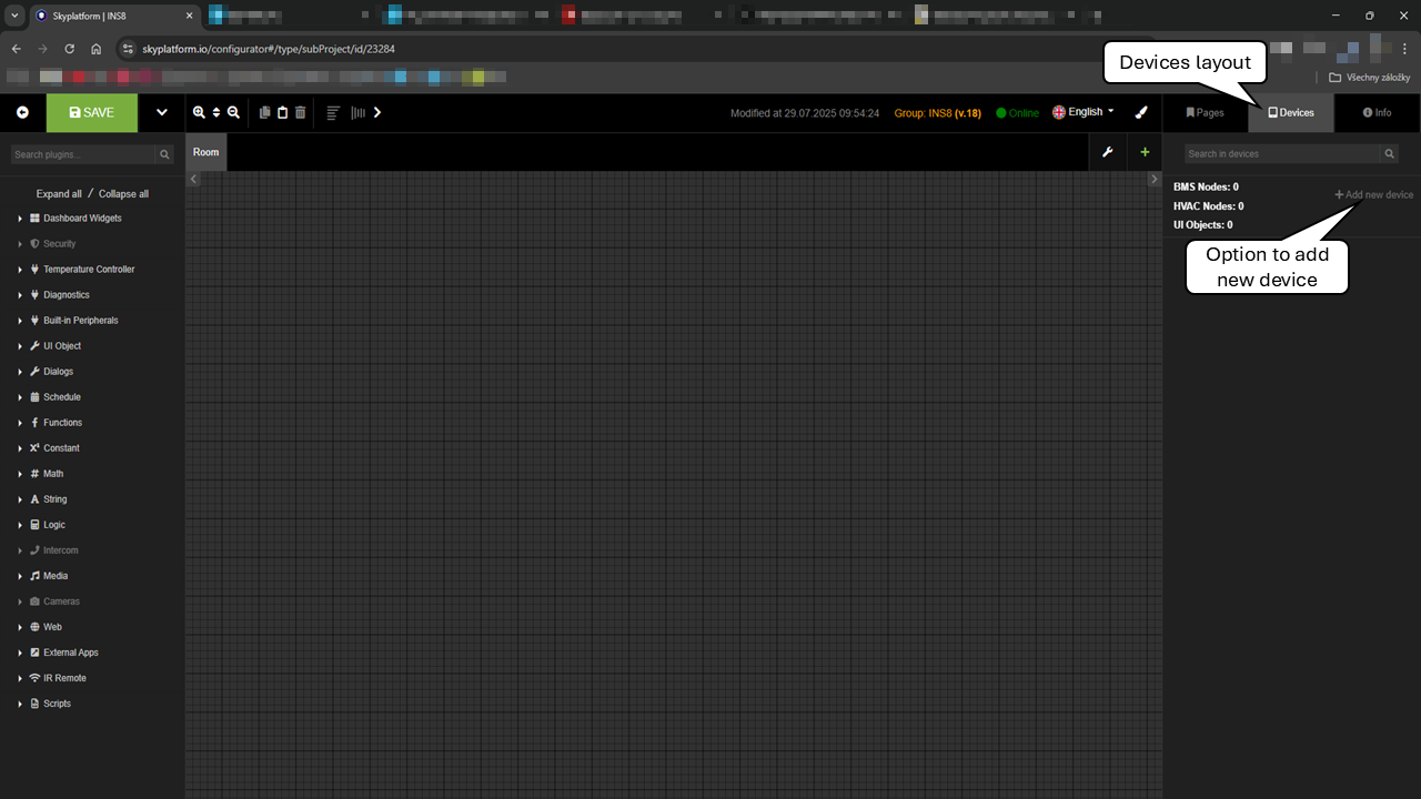
* In the opened project, select "Device" layout and click on "Add new device".
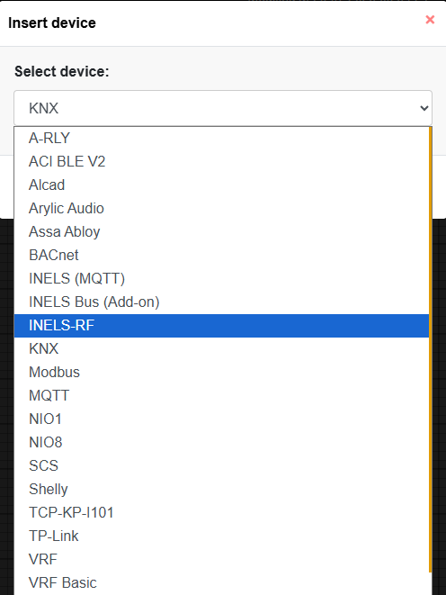
* In the pop-up window select device "iNELS RF"
* In the upcomming window, user needs to define specific information about gateway:
* ```
* **Gateway type**
* here you choose the gateway type you are going to configure
* There are 4 available types of gateway:
```

* ```
* **IP Address**
* define IP eddress of the chosen gateway
```
* ```
* **Port**
* standard port to be used is "9999"
```
* ```
* **Username / Password**
* credentials to access gateway
```
* ```
* **Search**
* function to search connected network to find all available wireless gateways
* choosing one in column "Select" and clicking "Save" button, will prefill the underlying form with gateway type, IP address and port. User needs to fill credetials only (if applicable)
```

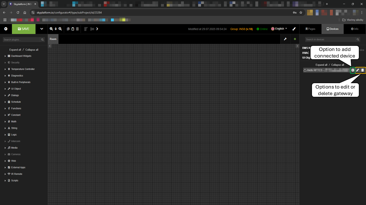
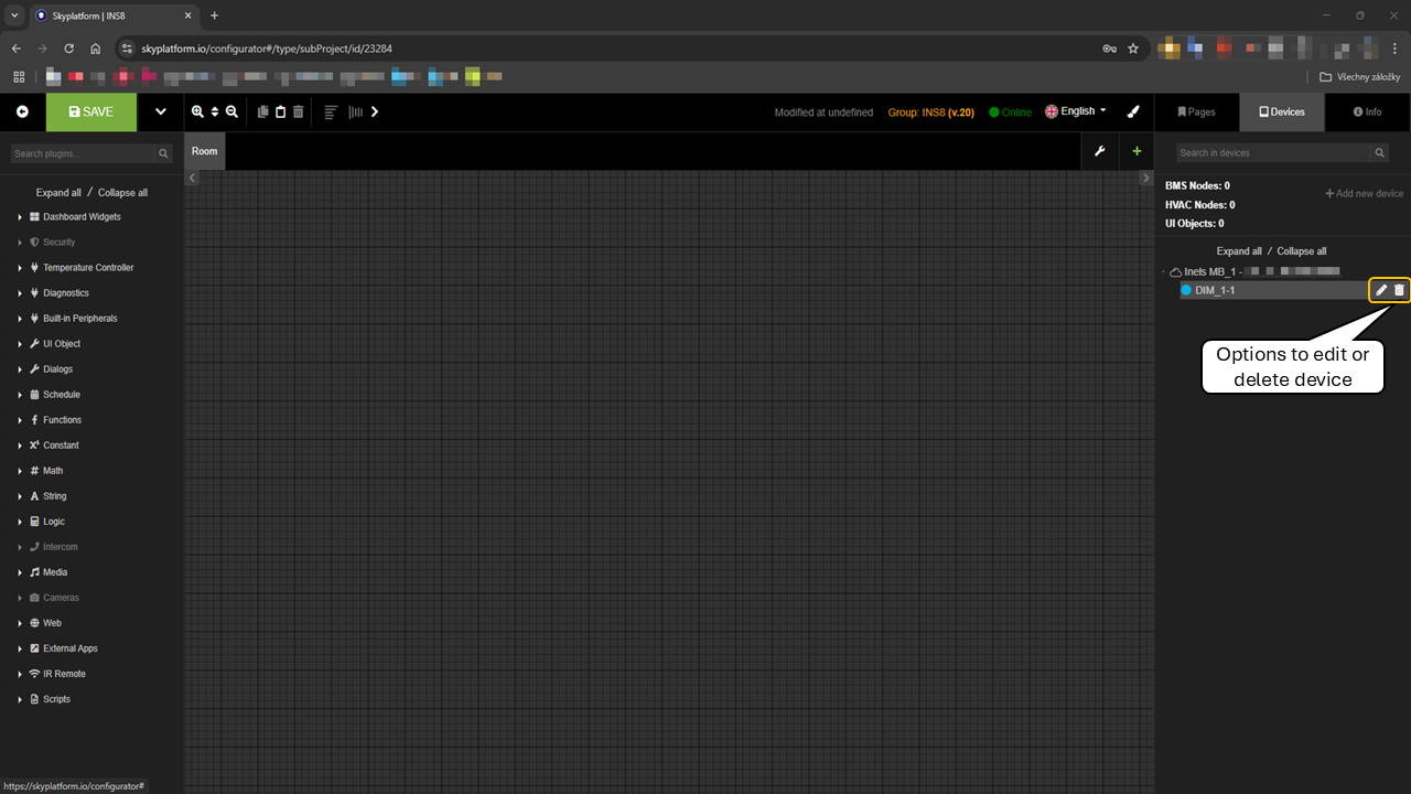
* Saved device will be seen in the device layout in format "\[gateway type] - \[IP address]:\[Port]". Gateway can be edited, deleted or user can add connected devices (*described in next chapters*)
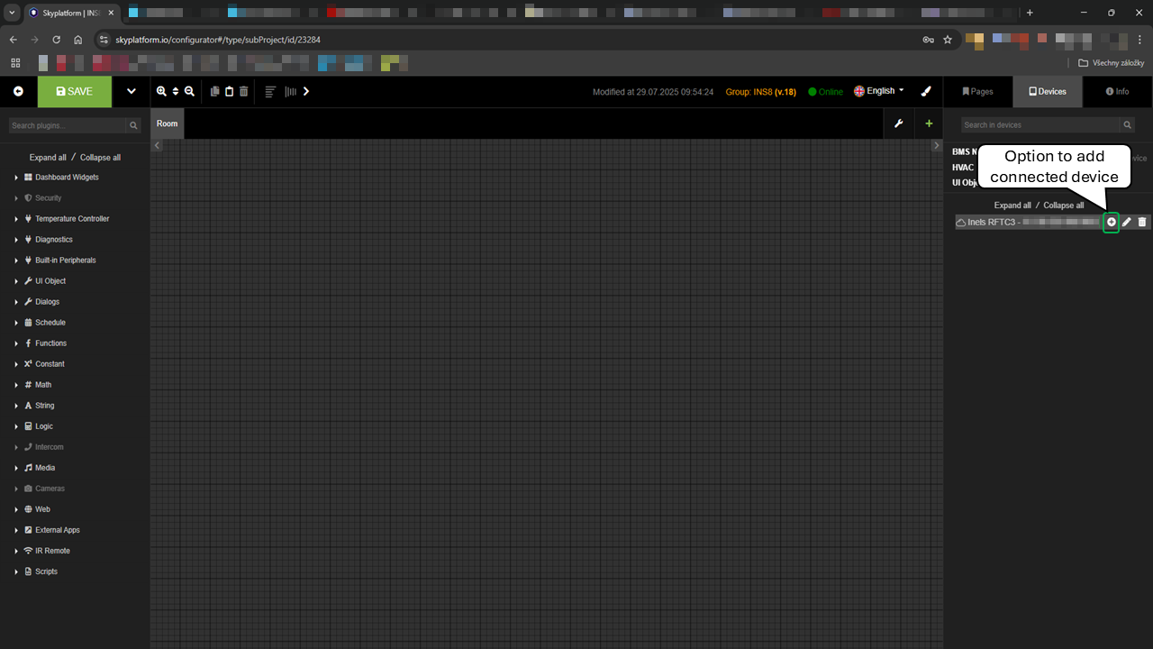
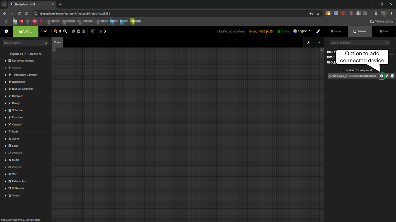
Once the iNELS Wireless gateway was defined, we can start adding connected devices:
* click on the "+" button next to the gateway ntroduction As gateways, components are also to 2 groups, communicating on diferrent protocols. A) iNELS Wireless Components are using iNELS RFIO and RFIO2 protocols for biderectional communication with gateway and between each other. Related components could be found [here](https://app.clickup.com/10544682/v/dc/a1tha-47995/a1tha-18375). B) iNELS Home Components is using iNELS RFIO3 protocol for biderectional communication with gateway and between each other. Related components could be found [here](https://app.clickup.com/10544682/v/dc/a1tha-47995/a1tha-18895).
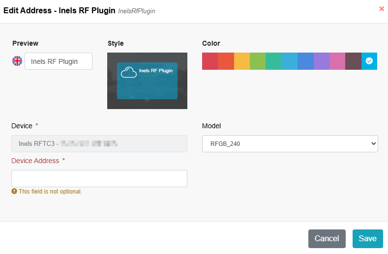
* On the Pop-up window user have to specify wireless unit to be used. Unit here to be understood not necessarely as a physical unit, but individual iNELS address on a chosen model (1 physical unit can have 1 or more iNELS addresses, e.g. RFSA-62B).
* ```
* **Model**
* User have to choose the corresponding model, that corresponds with physical device used in the project. Here is the list of predefined devices (_devices are described in particular chapters_)
```

* ```
* **Device Address**
* unique iNELS address shown on the physical unit (6 characters)
```
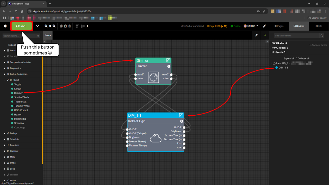
* Saved devices are vissible and accesible on "Devices" layout, under the gateway. User can edit or delete them anytime. 
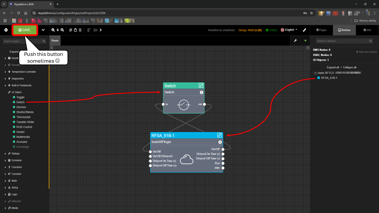
* Drag & drop the component from Devices layout into the Room layout and start wiring and defining conditions. Good practice is to save your project occasionally even during the creation process.
## Controllers
### RFWB-20
#### **On-wall button controller, 2 buttons**

#### **Inputs:**
* no inputs available on the unit
#### **Outputs:**
| **Sl No** | **Abbreviation** | **Content** | **Description** | **Unit** | **Value** |
| --------- | ---------------- | ---------------- | -------------------------------- | -------- | ----------------------------------------- |
| 1 | On/Off-1 | Switch button 1 | Acts on press of the buttons | - | Digital |
| 2 | On/Off-2 | Switch button 2 | - | Digital | |
| 3 | Battery status | Battery status | Status of the battery | - | Digital |
| 4 | RSSI | Signal strength | Signal Strength Indicator | - | (value/2)-102 |
| 5 | state | Connection state | Status of the gateway connection | - |
Connected / Gateway unreachable
|
### RFWB-40
#### **On-wall button controller, 4 buttons**

#### **Inputs:**
* no inputs available on the unit
#### **Outputs:**
| **Sl No** | **Abbreviation** | **Content** | **Description** | **Unit** | **Value** |
| --------- | ---------------- | ---------------- | -------------------------------- | -------- | ----------------------------------------- |
| 1 | On/Off-1 | Switch button 1 | Acts on press of the buttons | - | Digital |
| 2 | On/Off-2 | Switch button 2 | - | Digital | |
| 3 | On/Off-3 | Switch button 3 | - | Digital | |
| 4 | On/Off-4 | Switch button 4 | - | Digital | |
| 5 | Battery status | Battery status | Status of the battery | - | Digital |
| 6 | RSSI | Signal strength | Signal Strength Indicator | - | (value/2)-102 |
| 7 | state | Connection state | Status of the gateway connection | - |
Connected / Gateway unreachable
|
### RFGB-240
#### **On-wall button controller, 4 buttons**

#### **Inputs:**
* no inputs available on the unit
#### **Outputs:**
| **Sl No** | **Abbreviation** | **Content** | **Description** | **Unit** | **Value** |
| --------- | ---------------- | ---------------- | -------------------------------- | -------- | ----------------------------------------- |
| 1 | On/Off-1 | Switch button 1 | Acts on press of the buttons | - | Digital |
| 2 | On/Off-2 | Switch button 2 | - | Digital | |
| 3 | On/Off-3 | Switch button 3 | - | Digital | |
| 4 | On/Off-4 | Switch button 4 | - | Digital | |
| 5 | Battery status | Battery status | Status of the battery | - | Digital |
| 6 | RSSI | Signal strength | Signal Strength Indicator | - | (value/2)-102 |
| 7 | state | Connection state | Status of the gateway connection | - |
Connected / Gateway unreachable
|
## Switches
### RFSA-61B
#### **Switch unit, 1-channel**

#### **Inputs:**
| **Sl No** | **Abbreviation** | **Content** | **Description** | **Unit** | **Value** |
| --------- | ---------------- | -------------- | ------------------------------------- | -------- | --------------- |
| 1 | On/Off | Relay | Action on relay | - | Digital |
| 2 | On/Off (Delayed) | Delay On relay | Status of the delay function on relay | - | Digital |
| 3 | Delay On time | Delay On time | Delay time to start action on relay | s | Analog (2-3600) |
| 4 | Delay Off time | Delay Off time | Delay time to stop action on relay | s | Analog (2-3600) |
#### **Outputs:**
| **Sl No** | **Abbreviation** | **Content** | **Description** | **Unit** | **Value** |
| --------- | ---------------- | ---------------- | ----------------------------------- | -------- | ----------------------------------------- |
| 1 | On/Off | Relay | Action on relay | - | Digital |
| 2 | Delay On time | Delay On time | Delay time to start action on relay | s | Analog (2-3600) |
| 3 | Delay Off time | Delay Off time | Delay time to stop action on relay | s | Analog (2-3600) |
| 4 | RSSI | Signal strength | Signal Strength Indicator | - | (value/2)-102 |
| 5 | state | Connection state | Status of the gateway connection | - |
Connected / Gateway unreachable
|
### RFSA-62B
#### **Switch unit, 2-channels**

#### **Inputs:**
| **Sl No** | **Abbreviation** | **Content** | **Description** | **Unit** | **Value** |
| --------- | ---------------- | -------------- | ------------------------------------- | -------- | --------------- |
| 1 | On/Off | Relay | Action on relay | - | Digital |
| 2 | On/Off (Delayed) | Delay On relay | Status of the delay function on relay | - | Digital |
| 3 | Delay On time | Delay On time | Delay time to start action on relay | s | Analog (2-3600) |
| 4 | Delay Off time | Delay Off time | Delay time to stop action on relay | s | Analog (2-3600) |
#### **Outputs:**
| **Sl No** | **Abbreviation** | **Content** | **Description** | **Unit** | **Value** |
| --------- | ---------------- | ---------------- | ----------------------------------- | -------- | ----------------------------------------- |
| 1 | On/Off | Relay | Action on relay | - | Digital |
| 2 | Delay On time | Delay On time | Delay time to start action on relay | s | Analog (2-3600) |
| 3 | Delay Off time | Delay Off time | Delay time to stop action on relay | s | Analog (2-3600) |
| 4 | RSSI | Signal strength | Signal Strength Indicator | - | (value/2)-102 |
| 5 | state | Connection state | Status of the gateway connection | - |
Connected / Gateway unreachable
|
### RFSA-61M
#### **Switch unit, 1-channel**

#### **Inputs:**
| **Sl No** | **Abbreviation** | **Content** | **Description** | **Unit** | **Value** |
| --------- | ---------------- | -------------- | ------------------------------------- | -------- | --------------- |
| 1 | On/Off | Relay | Action on relay | - | Digital |
| 2 | On/Off (Delayed) | Delay On relay | Status of the delay function on relay | - | Digital |
| 3 | Delay On time | Delay On time | Delay time to start action on relay | s | Analog (2-3600) |
| 4 | Delay Off time | Delay Off time | Delay time to stop action on relay | s | Analog (2-3600) |
#### **Outputs:**
| **Sl No** | **Abbreviation** | **Content** | **Description** | **Unit** | **Value** |
| --------- | ---------------- | ---------------- | ----------------------------------- | -------- | ----------------------------------------- |
| 1 | On/Off | Relay | Action on relay | - | Digital |
| 2 | Delay On time | Delay On time | Delay time to start action on relay | s | Analog (2-3600) |
| 3 | Delay Off time | Delay Off time | Delay time to stop action on relay | s | Analog (2-3600) |
| 4 | RSSI | Signal strength | Signal Strength Indicator | - | (value/2)-102 |
| 5 | state | Connection state | Status of the gateway connection | - |
Connected / Gateway unreachable
|
### RFSA-66M
#### **Switch unit, 6-channels**

#### **Inputs:**
| **Sl No** | **Abbreviation** | **Content** | **Description** | **Unit** | **Value** |
| --------- | ---------------- | -------------- | ------------------------------------- | -------- | --------------- |
| 1 | On/Off | Relay | Action on relay | - | Digital |
| 2 | On/Off (Delayed) | Delay On relay | Status of the delay function on relay | - | Digital |
| 3 | Delay On time | Delay On time | Delay time to start action on relay | s | Analog (2-3600) |
| 4 | Delay Off time | Delay Off time | Delay time to stop action on relay | s | Analog (2-3600) |
#### **Outputs:**
| **Sl No** | **Abbreviation** | **Content** | **Description** | **Unit** | **Value** |
| --------- | ---------------- | ---------------- | ----------------------------------- | -------- | ----------------------------------------- |
| 1 | On/Off | Relay | Action on relay | - | Digital |
| 2 | Delay On time | Delay On time | Delay time to start action on relay | s | Analog (2-3600) |
| 3 | Delay Off time | Delay Off time | Delay time to stop action on relay | s | Analog (2-3600) |
| 4 | RSSI | Signal strength | Signal Strength Indicator | - | (value/2)-102 |
| 5 | state | Connection state | Status of the gateway connection | - |
|
### RFSAI-61B
#### **Switch unit** **with the input for external buttons**

#### **Inputs:**
| **Sl No** | **Abbreviation** | **Content** | **Description** | **Unit** | **Value** |
| --------- | ---------------- | -------------- | ------------------------------------- | -------- | --------------- |
| 1 | On/Off | Relay | Action on relay | - | Digital |
| 2 | On/Off (Delayed) | Delay On relay | Status of the delay function on relay | - | Digital |
| 3 | Delay On time | Delay On time | Delay time to start action on relay | s | Analog (2-3600) |
| 4 | Delay Off time | Delay Off time | Delay time to stop action on relay | s | Analog (2-3600) |
#### **Outputs:**
| **Sl No** | **Abbreviation** | **Content** | **Description** | **Unit** | **Value** |
| --------- | ---------------- | ---------------- | ----------------------------------- | -------- | ----------------------------------------- |
| 1 | On/Off | Relay | Action on relay | - | Digital |
| 2 | Delay On time | Delay On time | Delay time to start action on relay | s | Analog (2-3600) |
| 3 | Delay Off time | Delay Off time | Delay time to stop action on relay | s | Analog (2-3600) |
| 4 | RSSI | Signal strength | Signal Strength Indicator | - | (value/2)-102 |
| 5 | state | Connection state | Status of the gateway connection | - |
Connected / Gateway unreachable
|
### RFSAI-62B
#### **Switch unit** **with the input for external buttons**

#### **Inputs:**
| **Sl No** | **Abbreviation** | **Content** | **Description** | **Unit** | **Value** |
| --------- | ---------------- | -------------- | ------------------------------------- | -------- | --------------- |
| 1 | On/Off | Relay | Action on relay | - | Digital |
| 2 | On/Off (Delayed) | Delay On relay | Status of the delay function on relay | - | Digital |
| 3 | Delay On time | Delay On time | Delay time to start action on relay | s | Analog (2-3600) |
| 4 | Delay Off time | Delay Off time | Delay time to stop action on relay | s | Analog (2-3600) |
#### **Outputs:**
| **Sl No** | **Abbreviation** | **Content** | **Description** | **Unit** | **Value** |
| --------- | ---------------- | ---------------- | ----------------------------------- | -------- | ----------------------------------------- |
| 1 | On/Off | Relay | Action on relay | - | Digital |
| 2 | Delay On time | Delay On time | Delay time to start action on relay | s | Analog (2-3600) |
| 3 | Delay Off time | Delay Off time | Delay time to stop action on relay | s | Analog (2-3600) |
| 4 | RSSI | Signal strength | Signal Strength Indicator | - | (value/2)-102 |
| 5 | state | Connection state | Status of the gateway connection | - |
Connected / Gateway unreachable
|
### RFJA-32B
#### **Switch unit** **for the shutters**

#### **Inputs:**
| **Sl No** | **Abbreviation** | **Content** | **Description** | **Unit** | **Value** |
| --------- | ------------------ | ------------------ | ------------------------- | -------- | -------------- |
| 1 | Up | Relay up | Move upwards | - | Digital |
| 2 | Down | Relay down | Move downwards | - | Digital |
| 3 | Stop | Stop action | Stop of running movements | - | Digital |
| 4 | Position | Shutter position | Position of shutters | % | Analog (0-100) |
| 5 | Motor running time | Motor running time | Running time of the motor | s | Analog (2-240) |
#### **Outputs:**
| **Sl No** | **Abbreviation** | **Content** | **Description** | **Unit** | **Value** |
| --------- | ------------------ | ------------------ | ------------------------------ | -------- | ----------------------- |
| 1 | Up | Relay up | Move upwards | - | Digital |
| 2 | Down | Relay down | Move downwards | - | Digital |
| 3 | Position | Shutter position | Position of shutters | % | Analog (0-100) |
| 4 | Direction | Movement direction | Movement direction of shutters | - | Digital (0-Down / 1-Up) |
| 5 | Motor state | Motor status | Status of the motor action | - | Digital |
| 6 | Motor running time | Motor running time | Running time of the motor | s | Analog (2-240) |
| 7 | RSSI | Signal strength | Signal Strength Indicator | - | (value/2)-102 |
### RFUS-61
#### **Switch unit** **with increased protection**

#### **Inputs:**
| **Sl No** | **Abbreviation** | **Content** | **Description** | **Unit** | **Value** |
| --------- | ---------------- | -------------- | ------------------------------------- | -------- | --------------- |
| 1 | On/Off | Relay | Action on relay | - | Digital |
| 2 | On/Off (Delayed) | Delay On relay | Status of the delay function on relay | - | Digital |
| 3 | Delay On time | Delay On time | Delay time to start action on relay | s | Analog (2-3600) |
| 4 | Delay Off time | Delay Off time | Delay time to stop action on relay | s | Analog (2-3600) |
#### **Outputs:**
| **Sl No** | **Abbreviation** | **Content** | **Description** | **Unit** | **Value** |
| --------- | ---------------- | ---------------- | ----------------------------------- | -------- | ----------------------------------------- |
| 1 | On/Off | Relay | Action on relay | - | Digital |
| 2 | Delay On time | Delay On time | Delay time to start action on relay | s | Analog (2-3600) |
| 3 | Delay Off time | Delay Off time | Delay time to stop action on relay | s | Analog (2-3600) |
| 4 | RSSI | Signal strength | Signal Strength Indicator | - | (value/2)-102 |
| 5 | state | Connection state | Status of the gateway connection | - |
Connected / Gateway unreachable
|
### RFSC-61
#### **Switching socket-plug**

#### **Inputs:**
| **Sl No** | **Abbreviation** | **Content** | **Description** | **Unit** | **Value** |
| --------- | ---------------- | -------------- | ------------------------------------- | -------- | --------------- |
| 1 | On/Off | Relay | Action on relay | - | Digital |
| 2 | On/Off (Delayed) | Delay On relay | Status of the delay function on relay | - | Digital |
| 3 | Delay On time | Delay On time | Delay time to start action on relay | s | Analog (2-3600) |
| 4 | Delay Off time | Delay Off time | Delay time to stop action on relay | s | Analog (2-3600) |
#### **Outputs:**
| **Sl No** | **Abbreviation** | **Content** | **Description** | **Unit** | **Value** |
| --------- | ---------------- | ---------------- | ----------------------------------- | -------- | ----------------------------------------- |
| 1 | On/Off | Relay | Action on relay | - | Digital |
| 2 | Delay On time | Delay On time | Delay time to start action on relay | s | Analog (2-3600) |
| 3 | Delay Off time | Delay Off time | Delay time to stop action on relay | s | Analog (2-3600) |
| 4 | RSSI | Signal strength | Signal Strength Indicator | - | (value/2)-102 |
| 5 | state | Connection state | Status of the gateway connection | - |
Connected / Gateway unreachable
|
## Dimmers
### RFDAC-71
#### **Analog controller, 0(1)-10V**

#### **Inputs:**
| **Sl No** | **Abbreviation** | **Content** | **Description** | **Unit** | **Value** |
| --------- | ---------------- | ---------------- | ------------------------------------- | -------- | --------------- |
| 1 | On/Off | Relay | Action on relay | - | Digital |
| 2 | On/Off (Delayed) | Delay On relay | Status of the delay function on relay | - | Digital |
| 3 | Brightness | Brightness level | Level of the brightness (step 10%) | % | Analog (0-100) |
| 4 | Increase time | Increase time | Delay time of the increase function | s | Analog (2-1800) |
| 5 | Decrease time | Decrease time | Delay time of the decrease function | s | Analog (2-1800) |
#### **Outputs:**
| **Sl No** | **Abbreviation** | **Content** | **Description** | **Unit** | **Value** |
| --------- | ---------------- | ---------------- | ----------------------------------- | -------- | ----------------------------------------- |
| 1 | On/Off | Relay | Action on relay | - | Digital |
| 2 | Brightness | Brightness level | Level of the brightness (step 10%) | % | Analog (0-100) |
| 3 | Increase time | Increase time | Delay time of the increase function | s | Analog (2-1800) |
| 4 | Decrease time | Decrease time | Delay time of the decrease function | s | Analog (2-1800) |
| 5 | RSSI | Signal strength | Signal Strength Indicator | - | (value/2)-102 |
| 6 | state | Connection state | Status of the gateway connection | - |
Connected / Gateway unreachable
|
### RFDEL-71
#### **Universal dimmer, 1-channel**

#### **Inputs:**
| **Sl No** | **Abbreviation** | **Content** | **Description** | **Unit** | **Value** |
| --------- | ---------------- | ---------------- | ------------------------------------- | -------- | --------------- |
| 1 | On/Off | Relay | Action on relay | - | Digital |
| 2 | On/Off (Delayed) | Delay On relay | Status of the delay function on relay | - | Digital |
| 3 | Brightness | Brightness level | Level of the brightness (step 10%) | % | Analog (0-100) |
| 4 | Increase time | Increase time | Delay time of the increase function | s | Analog (2-1800) |
| 5 | Decrease time | Decrease time | Delay time of the decrease function | s | Analog (2-1800) |
#### **Outputs:**
| **Sl No** | **Abbreviation** | **Content** | **Description** | **Unit** | **Value** |
| --------- | ---------------- | ---------------- | ----------------------------------- | -------- | ----------------------------------------- |
| 1 | On/Off | Relay | Action on relay | - | Digital |
| 2 | Brightness | Brightness level | Level of the brightness (step 10%) | % | Analog (0-100) |
| 3 | Increase time | Increase time | Delay time of the increase function | s | Analog (2-1800) |
| 4 | Decrease time | Decrease time | Delay time of the decrease function | s | Analog (2-1800) |
| 5 | RSSI | Signal strength | Signal Strength Indicator | - | (value/2)-102 |
| 6 | state | Connection state | Status of the gateway connection | - |
Connected / Gateway unreachable
|
### RFDSC-71
#### **Dimming socket plug**

#### **Inputs:**
| **Sl No** | **Abbreviation** | **Content** | **Description** | **Unit** | **Value** |
| --------- | ---------------- | ---------------- | ------------------------------------- | -------- | --------------- |
| 1 | On/Off | Relay | Action on relay | - | Digital |
| 2 | On/Off (Delayed) | Delay On relay | Status of the delay function on relay | - | Digital |
| 3 | Brightness | Brightness level | Level of the brightness (step 10%) | % | Analog (0-100) |
| 4 | Increase time | Increase time | Delay time of the increase function | s | Analog (2-1800) |
| 5 | Decrease time | Decrease time | Delay time of the decrease function | s | Analog (2-1800) |
#### **Outputs:**
| **Sl No** | **Abbreviation** | **Content** | **Description** | **Unit** | **Value** |
| --------- | ---------------- | ---------------- | ----------------------------------- | -------- | ----------------------------------------- |
| 1 | On/Off | Relay | Action on relay | - | Digital |
| 2 | Brightness | Brightness level | Level of the brightness (step 10%) | % | Analog (0-100) |
| 3 | Increase time | Increase time | Delay time of the increase function | s | Analog (2-1800) |
| 4 | Decrease time | Decrease time | Delay time of the decrease function | s | Analog (2-1800) |
| 5 | RSSI | Signal strength | Signal Strength Indicator | - | (value/2)-102 |
| 6 | state | Connection state | Status of the gateway connection | - |
Connected / Gateway unreachable
|
### RFDALI-32
#### **DALI controller, for 32 addresses**

#### **Inputs:**
| **Sl No** | **Abbreviation** | **Content** | **Description** | **Unit** | **Value** |
| --------- | ---------------- | ---------------- | ------------------------------------- | -------- | --------------- |
| 1 | On/Off | Relay | Action on relay | - | Digital |
| 2 | On/Off (Delayed) | Delay On relay | Status of the delay function on relay | - | Digital |
| 3 | Brightness | Brightness level | Level of the brightness (step 10%) | % | Analog (0-100) |
| 4 | Increase time | Increase time | Delay time of the increase function | s | Analog (2-1800) |
| 5 | Decrease time | Decrease time | Delay time of the decrease function | s | Analog (2-1800) |
#### **Outputs:**
| **Sl No** | **Abbreviation** | **Content** | **Description** | **Unit** | **Value** |
| --------- | ---------------- | ---------------- | ----------------------------------- | -------- | ----------------------------------------- |
| 1 | On/Off | Relay | Action on relay | - | Digital |
| 2 | Brightness | Brightness level | Level of the brightness (step 10%) | % | Analog (0-100) |
| 3 | Increase time | Increase time | Delay time of the increase function | s | Analog (2-1800) |
| 4 | Decrease time | Decrease time | Delay time of the decrease function | s | Analog (2-1800) |
| 5 | RSSI | Signal strength | Signal Strength Indicator | - | (value/2)-102 |
| 6 | state | Connection state | Status of the gateway connection | - |
Connected / Gateway unreachable
|
### RFDA-73M/RGB
#### **Dimmer for LED (RGB) strips, 3-channels**

#### **Inputs:**
| **Sl No** | **Abbreviation** | **Content** | **Description** | **Unit** | **Value** |
| --------- | ---------------- | ---------------- | ---------------------------------- | -------- | -------------- |
| 1 | On/Off | Relay | Action on relay | - | Digital |
| 2 | Brightness | Brightness level | Level of the brightness (step 10%) | % | Analog (0-100) |
| 3 | RGB (hex) | RGB | RGB in hexadecimal format | - | Hexadecimal |
| 4 | Red | Red component | Level of the red color | - | Analog (0-255) |
| 5 | Green | Green component | Level of the red color | - | Analog (0-255) |
| 6 | Blue | Blue component | Level of the red color | - | Analog (0-255) |
| 7 | Demo | Demo mode | Status of the demo mode | - | Digital |
#### **Outputs:**
| **Sl No** | **Abbreviation** | **Content** | **Description** | **Unit** | **Value** |
| --------- | ---------------- | ---------------- | ---------------------------------- | -------- | ----------------------------------------- |
| 1 | On/Off | Relay | Action on relay | - | Digital |
| 2 | Brightness | Brightness level | Level of the brightness (step 10%) | % | Analog (0-100) |
| 3 | RGB (hex) | RGB | RGB in hexadecimal format | - | Hexadecimal |
| 4 | Red | Red component | Level of the red color | - | Analog (0-255) |
| 5 | Green | Green component | Level of the red color | - | Analog (0-255) |
| 6 | Blue | Blue component | Level of the red color | - | Analog (0-255) |
| 7 | Demo | Demo mode | Status of the demo mode | - | Digital |
| 8 | RSSI | Signal strength | Signal Strength Indicator | - | (value/2)-102 |
| 9 | state | Connection state | Status of the gateway connection | - |
Connected / Gateway unreachable
|
## Temperature Control (Thermostats, thermovalves)
### RFATV-2
#### **Wireless thermovalve**

#### **Inputs:**
| **Sl No** | **Abbreviation** | **Content** | **Description** | **Unit** | **Value** |
| --------- | ----------------- | ------------------ | ------------------------------------------------------------ | -------- | ------------- |
| 1 | setTemp | Relay | Action on relay | - | Digital |
| 2 | Window sensor | Window sensitivity | Sensitivity level to open window | - | Analog (0-3) |
| 3 | Window time (min) | Window time |
Time the window is assumed as opened (step 10 min)
| min | Analog (0-60) |
#### **Outputs:**
| **Sl No** | **Abbreviation** | **Content** | **Description** | **Unit** | **Value** |
| --------- | ----------------- | ------------------- | ----------------------------------------------------------------------------------- | -------- | ----------------------------------------- |
| 1 | setTemp | Relay | Action on relay | - | Digital |
| 2 | Current Temp | Current temperature | Measured temperature by the thermovalve | °C | Analog (0-50) |
| 3 | Valve | Open level | Level of the valve openness | % | Analog (0-100) |
| 4 | Window sensor | Window sensitivity | Sensitivity level to temperature decrease (detection of open window) | - | Analog (0-3) |
| 5 | Window time (min) | Window time |
Time the window is assumed as opened and heating is stopped (step 10 min)
| min | Analog (0-60) |
| 6 | Battery status | Battery status | Status of the battery | - | Digital |
| 7 | Window open | Window open state | Open state of the window | - | Digital |
| 8 | Error | Error state | Device in error state | - | Digital |
| 9 | RSSI | Signal strength | Signal Strength Indicator | - | (value/2)-102 |
| 10 | state | Connection state | Status of the gateway connection | - |
Connected / Gateway unreachable
|
### RFSTI-11B
#### **Switch unit with external temperature sensor**

#### **Inputs:**
| **Sl No** | **Abbreviation** | **Content** | **Description** | **Unit** | **Value** |
| --------- | ---------------- | ---------------------- | ------------------------------------------------- | -------- | ----------------- |
| 1 | On/Off | Relay | Action on relay | - | Digital |
| 2 | Offset | Temperature correction | Value to adjust measured temperature (step 0.1°C) | °C | Analog (-20 - 20) |
#### **Outputs:**
| **Sl No** | **Abbreviation** | **Content** | **Description** | **Unit** | **Value** |
| --------- | ---------------- | ---------------------- | ------------------------------------------------- | -------- | ----------------------------------------- |
| 1 | On/Off | Relay | Action on relay | - | Digital |
| 2 | Temperature | Temperature | Value of measured temperature (step 0.01°C) | °C | Analog (-25 - 55) |
| 3 | Offset | Temperature correction | Value to adjust measured temperature (step 0.1°C) | °C | Analog (-20 - 20) |
| 4 | RSSI | Signal strength | Signal Strength Indicator | - | (value/2)-102 |
| 5 | state | Connection state | Status of the gateway connection | - |
Connected / Gateway unreachable
|
### RFTI-20
#### **Temperature and humidity sensor**

#### **Inputs:**
* no inputs available on the unit
#### **Outputs:**
| **Sl No** | **Abbreviation** | **Content** | **Description** | **Unit** | **Value** |
| --------- | ---------------- | ---------------- | ------------------------------------------- | -------- | ----------------------------------------- |
| 1 | Temperature | Temperature | Value of measured temperature (step 0.01°C) | °C | Analog (-10 - 50) |
| 2 | Humidity | Humidity | Value of measured humidity (step 1%) | % | Analog (0 - 90) |
| 3 | RSSI | Signal strength | Signal Strength Indicator | - | (value/2)-102 |
| 4 | state | Connection state | Status of the gateway connection | - |
Connected / Gateway unreachable
|
## Sensors
### RFWD-100
#### **Window / Door detector**

#### **Inputs:**
* no inputs available on the unit
#### **Outputs:**
| **Sl No** | **Abbreviation** | **Content** | **Description** | **Unit** | **Value** |
| --------- | ---------------- | ---------------- | -------------------------------- | -------- | ----------------------------------------- |
| 1 | Alarm | Alarm state | Alarm detection | - | Digital |
| 2 | Tamper | Tamper state | Tamper detection | - | Digital |
| 3 | Battery status | Battery state | Status of the battery | - | Digital |
| 4 | RSSI | Signal strength | Signal Strength Indicator | - | (value/2)-102 |
| 5 | state | Connection state | Status of the gateway connection | - |
Connected / Gateway unreachable
|
### RFMD-100
#### **Motion detector**

#### **Inputs:**
* no inputs available on the unit
#### **Outputs:**
| **Sl No** | **Abbreviation** | **Content** | **Description** | **Unit** | **Value** |
| --------- | ---------------- | ---------------- | -------------------------------- | -------- | ----------------------------------------- |
| 1 | Alarm | Alarm state | Alarm detection | - | Digital |
| 2 | Tamper | Tamper state | Tamper detection | - | Digital |
| 3 | Battery status | Battery state | Status of the battery | - | Digital |
| 4 | RSSI | Signal strength | Signal Strength Indicator | - | (value/2)-102 |
| 5 | state | Connection state | Status of the gateway connection | - |
Connected / Gateway unreachable
|
### RFMD-200
#### **Motion detector for ceiling mounting**

#### **Inputs:**
* no inputs available on the unit
#### **Outputs:**
| **Sl No** | **Abbreviation** | **Content** | **Description** | **Unit** | **Value** |
| --------- | ---------------- | ---------------- | -------------------------------- | -------- | ----------------------------------------- |
| 1 | Alarm | Alarm state | Alarm detection | - | Digital |
| 2 | Battery status | Battery state | Status of the battery | - | Digital |
| 3 | RSSI | Signal strength | Signal Strength Indicator | - | (value/2)-102 |
| 4 | state | Connection state | Status of the gateway connection | - |
Connected / Gateway unreachable
|
## iNELS Home
### How to use it on Sky Platform?
Once the iNELS Wireless gateway was defined, we can start adding connected devices:
* click on the "+" button next to the gateway
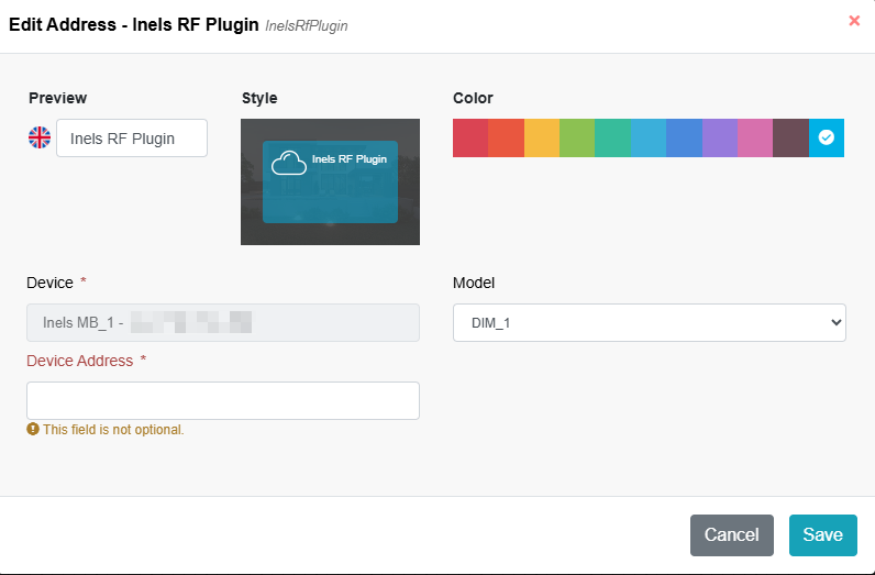
* On the Pop-up window user have to specify wireless unit to be used. Unit here to be understood not necessarely as a physical unit, but individual iNELS address on a chosen model (1 physical unit can have 1 or more iNELS addresses, e.g. RFSA-62B).
*
* ```
* **Model**
* User have to choose the corresponding model, that corresponds with physical device used in the project. Here is the list of predefined devices (_devices are described in particular chapters_)
```

* ```
* **Device Address**
* unique iNELS address shown on the physical unit (6 characters)
```
* Saved devices are vissible and accesible on "Devices" layout, under the gateway. User can edit or delete them anytime.
*
* Drag & drop the component from Devices layout into the Room layout and start wiring and defining conditions. Good practice is to save your project occasionally even during the creation process.
## Controllers
### TB-2
#### **On-wall button controller, 2 buttons**

#### **Inputs:**
* no inputs available on the unit
#### **Outputs:**
| **Sl No** | **Abbreviation** | **Content** | **Description** | **Unit** | **Value** |
| --------- | ---------------- | ---------------- | -------------------------------- | -------- | ----------------------------------------- |
| 1 | On/Off-1 | Switch button 1 | Acts on press of the buttons | - | Digital |
| 2 | On/Off-2 | Switch button 2 | - | Digital | |
| 3 | Battery status | Battery status | Status of the battery | - | Digital |
| 4 | RSSI | Signal strength | Signal Strength Indicator | - | (value/2)-102 |
| 5 | state | Connection state | Status of the gateway connection | - |
Connected / Gateway unreachable
|
### FB-4
#### **On-wall button controller, 4 buttons**

#### **Inputs:**
* no inputs available on the unit
#### **Outputs:**
| **Sl No** | **Abbreviation** | **Content** | **Description** | **Unit** | **Value** |
| --------- | ---------------- | ---------------- | -------------------------------- | -------- | ----------------------------------------- |
| 1 | On/Off-1 | Switch button 1 | Acts on press of the buttons | - | Digital |
| 2 | On/Off-2 | Switch button 2 | - | Digital | |
| 3 | On/Off-3 | Switch button 3 | - | Digital | |
| 4 | On/Off-4 | Switch button 4 | - | Digital | |
| 5 | Battery status | Battery status | Status of the battery | - | Digital |
| 6 | RSSI | Signal strength | Signal Strength Indicator | - | (value/2)-102 |
| 7 | state | Connection state | Status of the gateway connection | - |
Connected / Gateway unreachable
|
### KF-4
#### **Key fob, 4-channels**

#### **Inputs:**
* no inputs available on the unit
#### **Outputs:**
| **Sl No** | **Abbreviation** | **Content** | **Description** | **Unit** | **Value** |
| --------- | ---------------- | ---------------- | -------------------------------- | -------- | ----------------------------------------- |
| 1 | On/Off-1 | Switch button 1 | Acts on press of the buttons | - | Digital |
| 2 | On/Off-2 | Switch button 2 | - | Digital | |
| 3 | On/Off-3 | Switch button 3 | - | Digital | |
| 4 | On/Off-4 | Switch button 4 | - | Digital | |
| 5 | Battery status | Battery status | Status of the battery | - | Digital |
| 6 | RSSI | Signal strength | Signal Strength Indicator | - | (value/2)-102 |
| 7 | state | Connection state | Status of the gateway connection | - |
Connected / Gateway unreachable
|
## Switches
### OS-1
#### **Switch unit, 1-channel**

#### **Inputs:**
| **Sl No** | **Abbreviation** | **Content** | **Description** | **Unit** | **Value** |
| --------- | ---------------- | -------------- | ------------------------------------- | -------- | --------------- |
| 1 | On/Off | Relay | Action on relay | - | Digital |
| 2 | On/Off (Delayed) | Delay On relay | Status of the delay function on relay | - | Digital |
| 3 | Delay On time | Delay On time | Delay time to start action on relay | s | Analog (2-3600) |
| 4 | Delay Off time | Delay Off time | Delay time to stop action on relay | s | Analog (2-3600) |
#### **Outputs:**
| **Sl No** | **Abbreviation** | **Content** | **Description** | **Unit** | **Value** |
| --------- | ---------------- | ---------------- | ----------------------------------- | -------- | ----------------------------------------- |
| 1 | On/Off | Relay | Action on relay | - | Digital |
| 2 | Delay On time | Delay On time | Delay time to start action on relay | s | Analog (2-3600) |
| 3 | Delay Off time | Delay Off time | Delay time to stop action on relay | s | Analog (2-3600) |
| 4 | RSSI | Signal strength | Signal Strength Indicator | - | (value/2)-102 |
| 5 | state | Connection state | Status of the gateway connection | - |
Connected / Gateway unreachable
|
### DS-2
#### **Switch unit, 2-channels**

#### **Inputs:**
| **Sl No** | **Abbreviation** | **Content** | **Description** | **Unit** | **Value** |
| --------- | ---------------- | -------------- | ------------------------------------- | -------- | --------------- |
| 1 | On/Off | Relay | Action on relay | - | Digital |
| 2 | On/Off (Delayed) | Delay On relay | Status of the delay function on relay | - | Digital |
| 3 | Delay On time | Delay On time | Delay time to start action on relay | s | Analog (2-3600) |
| 4 | Delay Off time | Delay Off time | Delay time to stop action on relay | s | Analog (2-3600) |
#### **Outputs:**
| **Sl No** | **Abbreviation** | **Content** | **Description** | **Unit** | **Value** |
| --------- | ---------------- | ---------------- | ----------------------------------- | -------- | ----------------------------------------- |
| 1 | On/Off | Relay | Action on relay | - | Digital |
| 2 | Delay On time | Delay On time | Delay time to start action on relay | s | Analog (2-3600) |
| 3 | Delay Off time | Delay Off time | Delay time to stop action on relay | s | Analog (2-3600) |
| 4 | RSSI | Signal strength | Signal Strength Indicator | - | (value/2)-102 |
| 5 | state | Connection state | Status of the gateway connection | - |
Connected / Gateway unreachable
|
### SB-2
#### **Switch unit** **for the shutters**

#### **Inputs:**
| **Sl No** | **Abbreviation** | **Content** | **Description** | **Unit** | **Value** |
| --------- | ------------------ | ------------------ | ------------------------- | -------- | -------------- |
| 1 | Up | Relay up | Move upwards | - | Digital |
| 2 | Down | Relay down | Move downwards | - | Digital |
| 3 | Stop | Stop action | Stop of running movements | - | Digital |
| 4 | Position | Shutter position | Position of shutters | % | Analog (0-100) |
| 5 | Motor running time | Motor running time | Running time of the motor | s | Analog (2-240) |
#### **Outputs:**
| **Sl No** | **Abbreviation** | **Content** | **Description** | **Unit** | **Value** |
| --------- | ------------------ | ------------------ | ------------------------------ | -------- | ----------------------- |
| 1 | Up | Relay up | Move upwards | - | Digital |
| 2 | Down | Relay down | Move downwards | - | Digital |
| 3 | Position | Shutter position | Position of shutters | % | Analog (0-100) |
| 4 | Direction | Movement direction | Movement direction of shutters | - | Digital (0-Down / 1-Up) |
| 5 | Motor state | Motor status | Status of the motor action | - | Digital |
| 6 | Motor running time | Motor running time | Running time of the motor | s | Analog (2-240) |
| 7 | RSSI | Signal strength | Signal Strength Indicator | - | (value/2)-102 |
## Dimmers
### DIM-1
#### **Universal dimmer, 1-channel**

#### **Inputs:**
| **Sl No** | **Abbreviation** | **Content** | **Description** | **Unit** | **Value** |
| --------- | ---------------- | ---------------- | ------------------------------------- | -------- | --------------- |
| 1 | On/Off | Relay | Action on relay | - | Digital |
| 2 | On/Off (Delayed) | Delay On relay | Status of the delay function on relay | - | Digital |
| 3 | Brightness | Brightness level | Level of the brightness (step 10%) | % | Analog (0-100) |
| 4 | Increase time | Increase time | Delay time of the increase function | s | Analog (2-1800) |
| 5 | Decrease time | Decrease time | Delay time of the decrease function | s | Analog (2-1800) |
#### **Outputs:**
| **Sl No** | **Abbreviation** | **Content** | **Description** | **Unit** | **Value** |
| --------- | ---------------- | ---------------- | ----------------------------------- | -------- | ----------------------------------------- |
| 1 | On/Off | Relay | Action on relay | - | Digital |
| 2 | Brightness | Brightness level | Level of the brightness (step 10%) | % | Analog (0-100) |
| 3 | Increase time | Increase time | Delay time of the increase function | s | Analog (2-1800) |
| 4 | Decrease time | Decrease time | Delay time of the decrease function | s | Analog (2-1800) |
| 5 | RSSI | Signal strength | Signal Strength Indicator | - | (value/2)-102 |
| 6 | state | Connection state | Status of the gateway connection | - |
Connected / Gateway unreachable
|
## Converter
### IN-4
#### **Input contact converter**

#### **Inputs:**
* no inputs available on the unit
#### **Outputs:**
| **Sl No** | **Abbreviation** | **Content** | **Description** | **Unit** | **Value** |
| --------- | ---------------- | ---------------- | -------------------------------- | -------- | ----------------------------------------- |
| 1 | On/Off-1 | Switch button 1 | Acts on press of the buttons | - | Digital |
| 2 | On/Off-2 | Switch button 2 | - | Digital | |
| 3 | On/Off-3 | Switch button 3 | - | Digital | |
| 4 | On/Off-4 | Switch button 4 | - | Digital | |
| 5 | Battery status | Battery status | Status of the battery | - | Digital |
| 6 | RSSI | Signal strength | Signal Strength Indicator | - | (value/2)-102 |
| 7 | state | Connection state | Status of the gateway connection | - |
Connected / Gateway unreachable
|
## Sensors
### WDC-1
#### **Window / Door detector**

#### **Inputs:**
* no inputs available on the unit
#### **Outputs:**
| **Sl No** | **Abbreviation** | **Content** | **Description** | **Unit** | **Value** |
| --------- | ---------------- | ---------------- | -------------------------------- | -------- | ----------------------------------------- |
| 1 | Alarm | Alarm state | Alarm detection | - | Digital |
| 2 | Tamper | Tamper state | Tamper detection | - | Digital |
| 3 | Battery status | Battery state | Status of the battery | - | Digital |
| 4 | RSSI | Signal strength | Signal Strength Indicator | - | (value/2)-102 |
| 5 | state | Connection state | Status of the gateway connection | - |
Connected / Gateway unreachable
|
### PD-1
#### **Motion detector for ceiling mounting**

#### **Inputs:**
* no inputs available on the unit
#### **Outputs:**
| **Sl No** | **Abbreviation** | **Content** | **Description** | **Unit** | **Value** |
| --------- | ---------------- | ---------------- | -------------------------------- | -------- | ----------------------------------------- |
| 1 | Alarm | Alarm state | Alarm detection | - | Digital |
| 2 | Battery status | Battery state | Status of the battery | - | Digital |
| 3 | RSSI | Signal strength | Signal Strength Indicator | - | (value/2)-102 |
| 4 | state | Connection state | Status of the gateway connection | - |
Connected / Gateway unreachable
|
---
# Agent Instructions
This documentation is published with GitBook. GitBook is the documentation platform designed so that both humans and AI agents can read, navigate, and reason over technical content effectively. Learn more at gitbook.com.
## Querying This Documentation
If you need additional information that is not directly available in this page, you can query the documentation dynamically by asking a question.
Perform an HTTP GET request on the current page URL with the `ask` query parameter, and the optional `goal` query parameter:
```
GET https://wiki.inels.com/inels-bus/inspinia/inels-integration-to-skyplatform/inels-wireless-on-sky-platform.md?ask=&goal=
```
`ask` is the immediate question: it should be specific, self-contained, and written in natural language.
`goal` is optional and describes the broader end goal you are ultimately trying to accomplish on behalf of the user. GitBook uses it to tailor the answer towards what is most useful for that goal.
The response will contain a direct answer to the question and relevant excerpts and sources from the documentation.
Use this mechanism when the answer is not explicitly present in the current page, you need clarification or additional context, or you want to retrieve related documentation sections.