> For the complete documentation index, see [llms.txt](https://wiki.inels.com/llms.txt). Markdown versions of documentation pages are available by appending `.md` to page URLs; this page is available as [Markdown](https://wiki.inels.com/inels-bus/technical-manual-products/switching-actuators/sa3-01b-sa3-02b.md).
# SA3-01B/SA3-02B
## Overview of devices
{% hint style="info" %}
*An overview of the product design and usage. Includes circuit diagrams, terminal details, etc.,*
{% endhint %}


### **Key Features**
**Switching Capability:** Designed for switching one (SA3-01B) or two (SA3-02B) appliances and loads. Utilizes relay outputs with potentialless contacts.
**SA3-01B Specifications:** SA3-01B includes 1 relay with a potentialless contact.Maximum load: 16 A/4000 VA/AC1.
**SA3-02B Specifications:** SA3-02B includes 2 relays with potentialless contacts.
\- Maximum load: 8 A/2000 VA/AC1.
**Independent Control:** Output contacts are separately controllable and addressable.
**Versatile Applications:** SA3-02B actuator can control a 230 V drive (e.g., blinds, shutters, awnings). Changeover contacts allow securing locking hardware options while switching on phase two outputs.
**Temperature Input:** Equipped with a temperature input for connecting an external two-wire temperature sensor TC/TZ (see accessories).
**Output Status Indication:** LED on the front panel signals the state of each output.
**Contact Material:** SA3 is normally supplied with AgSnO2 contact material.
**Installation Details:** SA3-01B, SA3-02B are designed for mounting into the installation box.
### Exemplary circuit diagram/ Wiring Diagram

***
## Compatibility chart ( CU, minimal FW version and Integration)
{% hint style="info" %}
*The chart illustrates the compatibility between switching actuator and various central units, firmware versions, and integration options*
{% endhint %}
| SL No | Support Central units | Support FW | Support in MQTT | Support in HASS |
| ----- | --------------------- | ----------- | --------------- | --------------- |
| 1 | CU3-01M | 02.A0.00 | NA | NA |
| 2 | CU3-02M | 02.A0.00 | NA | NA |
| 3 | CU3-07M | 02.A0.00 | Yes | Yes |
| 4 | CU3-08M | 02.A0.00 | Yes | Yes |
| 6 | CU3-09M | Preparation | Preparation | Preparation |
| 7 | CU3-10M | Preparation | Preparation | Preparation |
***
## Programming in iDM
**Introduction**
iNELS Design Manager, or IDM3, is for programming iNELS units. This software serves as the platform for configuring device parameters, defining functions, and executing the programming required for iNELS units.
Device parameters, such as sensor range and thresholds, backlights, and operational modes, can be easily adjusted within the IDM3.
The process of programming in IDM3 typically involves defining functions and establishing logical connections between different devices. This allows for the creation of automation scenarios and the implementation of intelligent control strategies.
**Starting up**
Select the "***blue control icon"*** as shown in ***Fig 1*** > Clicking on the option ***"New project from default template“*** allows you to create a new project from a predefined template.
Select the "***Device manager"*** (***Fig 1***)> Add "***New unit*** "> Select the central unit > Add "***New*** ***unit"***>Select the "***Internal-Master/ BUS">*** Add "***New unit*** "> Add the devices> Click on the devices to see the "***Parameters"***.

**Parameters:**
**Parameters** in the iNELS devices refer to the measurable factors or characteristics that define the behavior or performance of the device. These could include electrical properties, physical dimensions, environmental conditions, and various other specifications depending on the type of device.
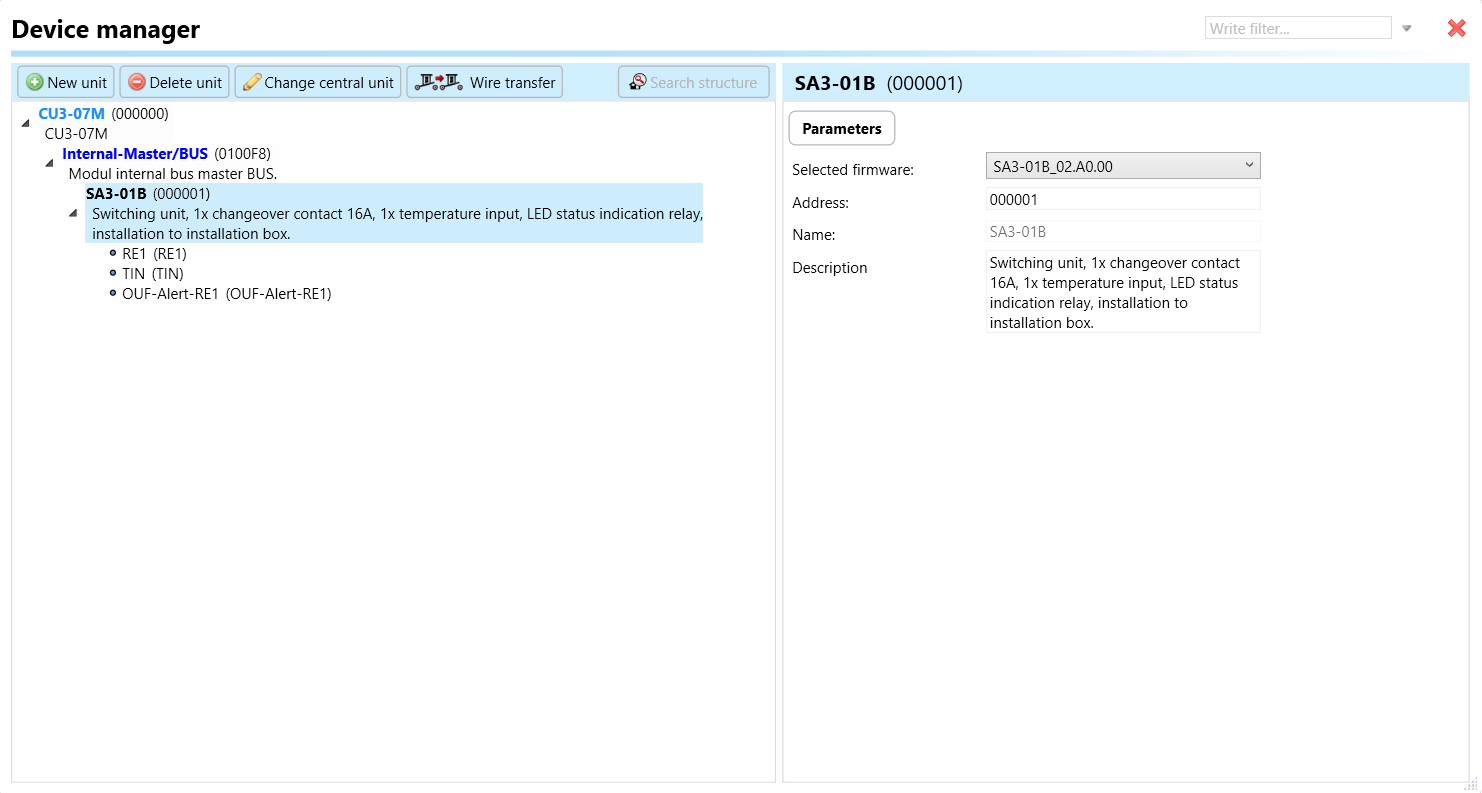
These are settings specific to individual devices within your automation system.The specific parameters of the SA3-01B and SA3-02B in the iDM as shown in ***Fig.2 and Fig.3*** respectively.
Fig.2: Parameters of SA3-01B
Clicking on the SA3-01B, SA3-02B (***Fig.2, Fig.3***), will navigate to the selected firmware, unit address, name, and description, along with other parameters as described below.
{% hint style="danger" %}
*It is important to add the device address for proper communication with the unit. The Hexadecimal device address can be find from the device.*
{% endhint %}
1. **RE1-** Relays are means of remotely controlling various electrical loads, such as lights or other devices. It acts as a switch that can open or close electrical circuits, allowing or interrupting the flow of power to connected devices.

* **Invert output:** "Invert output" refers to the ability to change the state of the output signal. When the output is inverted, a command that would normally turn the output on would instead turn it off, and vice versa.
* **Use default state:** In the context of a switching actuator, the term "default state" pertains to the pre-established or initial condition that the actuator adopts in the absence of communication from the bus or central unit. Enabling this function ensures that the relay automatically assumes its default state, which is set to OFF.
* **Default output state:** Upon choosing the "use default state" option, you will be prompted to specify the default output state. This refers to the pre-established or initial condition that the actuator adopts when there is no communication from the bus stop or central unit. Upon selecting this function, the relay will transition to its default output state, which, in this case, is set to ON.
* **Switch limit:** The switch limit parameter establishes the highest allowable frequency of relay switching per minute. If the number of switch occurrences surpasses this limit within a minute, the relay will not be triggered.
**2. TIN (Temperature Input)**: TIN refers to the temperature input feature in the actuator, allowing connection to an external two-wire temperature sensor (TC/TZ).
* **Sensor Type:** Sensor Type parameter specifies the type of temperature sensor connected to TIN. There are two types of sensors such TC and TZ. It ensures compatibility and proper calibration with the temperature sensor used.
* **Offset Temperature:** Offset Temperature parameter allows for calibration adjustments to compensate for any temperature measurement discrepancies. It ensures accurate temperature readings by fine-tuning the sensor's output.
* **Minimal Temperature:** Minimal Temperature parameter sets the lower limit for acceptable temperature readings from the connected sensor. It defines the minimum temperature threshold that triggers sensor responses or actions.
* **Maximal Temperature:** Maximal Temperature parameter sets the upper limit for acceptable temperature readings from the connected sensor. It establishes the maximum temperature threshold that triggers sensor responses or actions.
* **Average Time :** Defines the time period over which multiple temperature readings are averaged to obtain a stable and accurate measurement.
**3. OUF-Alert-RE1**: This parameter serves as an indicator for alert conditions associated with relay output 1 on the switching actuator. The alert is activated when the switching limit surpasses the configured threshold in any of the relay outputs. Upon activation, this alert signals users about a fault in one of the relay outputs, prompting them to investigate and take corrective measures. This is crucial to prevent potential damage to connected loads or the device itself.
**SA3-02B**

1. **Switch Limit:** The switch limit parameter establishes the highest allowable frequency of relay switching per minute. If the number of switch occurrences surpasses this limit within a minute, the relay will not be triggered.
2. **RE1-RE2: Blocking of Group Parallel Switching**: This function is responsible for preventing or halting the simultaneous switching of a relay in parallel with other relays within the designated group. For instance, if you designate RE1, RE2, to Blocking group of parallel switching- 1, none of these relays will switch on concurrently. This feature proves useful when connecting these relays to two distinct fans in an air conditioning system. If Fan 1 is activated, Fans 2 will not switch on in parallel, effectively safeguarding the fans from simultaneous switching
3. **RE1, 2-** Relays are means of remotely controlling various electrical loads, such as lights or other devices. It acts as a switch that can open or close electrical circuits, allowing or interrupting the flow of power to connected devices.
* **Invert output:** "Invert output" refers to the ability to change the state of the output signal. When the output is inverted, a command that would normally turn the output on would instead turn it off, and vice versa.
* **Use default state:** In the context of a switching actuator, the term "default state" pertains to the pre-established or initial condition that the actuator adopts in the absence of communication from the bus or central unit. Enabling this function ensures that the relay automatically assumes its default state, which is set to OFF.
* **Default output state:** Default Output State Selection: Upon choosing the "use default state" option, you will be prompted to specify the default output state. This refers to the pre-established or initial condition that the actuator adopts when there is no communication from the bus stop or central unit. Upon selecting this function, the relay will transition to its default output state, which, in this case, is set to ON.
* **Switch limit:** The switch limit parameter establishes the highest allowable frequency of relay switching per minute. If the number of switch occurrences surpasses this limit within a minute, the relay will not be triggered.
{% hint style="info" %}
For undefined parameters please refer to the parameters of SA3-01B
{% endhint %}
***
## Exports for iNELS Cloud and APP
**Setting Up Control and Monitoring for iNELS Cloud and iNELS App**
It is possible to control and monitor all the bus units in iNELS cloud and iNELS app. There are two stages to set up this function. Stage one is to do configuration in iDM3 and stage 2 is to do Configuration in iNELS cloud page and iNELS app.
#### Configuration in iDM3.
**1. Unit and Parameter Selection:**
Begin by accessing the iDM3 interface on your PC connected to CU. Navigate to the Device Manager section and carefully select the units and parameters you wish to control. This step is essential for determining what gets exported to the iNELS cloud and app.
**2. CU Configuration and Third-Party Settings :**
After the above step, go to the CU configuration in the iDM3, and select the page for third-party settings.
Inside the third-party settings page, designate the port for cloud connection. Set the mode of operation and choose the numerical system as hexadecimal. Pay close attention to verifying and configuring all essential parameters for successful cloud export.

**3. Cloud Settings:**
Move on to the Cloud Settings section within iDM3.
Input the details of your iNELS cloud account. If you haven't created one, utilize the "New User" tab on the iNELS Cloud web page to establish a free account. ([Inels Cloud - ElkoEP](https://inels.cloud/auth/login)).
Select the mode and input the cloud account credentials. Save the project to the central unit to generate and store the export project file in the iNELS cloud account.

#### Configuration in iNELS cloud page and iNELS App.
**1. Online Status Verification:**
Once the cloud credentials and export settings in iDM3 are configured successfully, check the iNELS cloud account's Gateway section. Confirm that the Central Unit (CU) is online and that the export file has been automatically sent to the cloud under your account.

**2. Device Creation in Cloud Platform:**
In the cloud platform, you have to create new devices in order to control it remotely.
In the device tab, you will find the add device button, which can be used to associate export elements from IDM with the required types and icons.

After entering any name of the device, you select the icon, the MAC address of the communication gateway (in this case CU3), a specific type of device and the address of a specific function and element from the iNELS BUS system.
{% hint style="danger" %}
*In order to be able to use the iNELS application to control the devices from CU over the local network or the cloud, it is necessary to create a room for bus devices for each central unit and add the devices into the room.*
{% endhint %}
Follow these steps meticulously to ensure a seamless configuration process for controlling and monitoring all bus units through iNELS cloud and iNELS app.
***
## 3rd Party Integration with iNELS BUS
#### 3rd Party Integration (MQTT)
* iNELS units support MQTT integration on central units CU3-07M, CU3-08M, CU3-09M, and CU3-10M. It is necessary to select the devices and parameters for 3rd party integration on the device manager in the iDM.
* Please note that you have an MQTT broker (local or cloud) running in the installation for this integration.
* After you have a working MQTT broker you need to configure iNELS Central units to communicate with it. If you have no knowledge of what MQTT is, you can learn about it from MQTT Essentials articles.
* There is a pre-installed MQTT broker in the iNLES bridge, it can be used to connect the iNELS Central units for integration in your projects.
**Configuration in iDM3: Select units of 3rd Party integration.**
1. **Unit and Parameter Selection:**
Begin by accessing the iDM3 interface on your PC connected to CU. Navigate to the Device Manager section and carefully select the units and parameters you wish to control. This step is essential for determining what gets exported to the 3rd party integration via MQTT.
2\. **CU Configuration and Third-Party Settings :**
After the above step, go to the CU configuration in the iDM3, and select the page for third party settings.
Inside the third-party settings page, designate the port for third-party connection. Set the mode of operation and choose the numerical system as hexadecimal. Pay close attention to verifying and configuring all essential parameters for successful third-party integration.

3\. **MQTT Settings:**
Move on to the MQTT Settings section within iDM3.
Input the details of your MQTT broker.
Select the mode and input the broker credentials such as IP, port username and password. Save the project to the central unit.

#### MQTT payload
For MQTT payload description please refer the link below.\
## Appendices
{% hint style="info" %}
*Provide any optional, supplementary information that may help in providing a more comprehensive understanding of the product feature*
{% endhint %}
{% embed url="" %}
Datasheet- SA3-01B
{% endembed %}
{% embed url="" %}
Datasheet- SA3-02B
{% endembed %}
---
# Agent Instructions
This documentation is published with GitBook. GitBook is the documentation platform designed so that both humans and AI agents can read, navigate, and reason over technical content effectively. Learn more at gitbook.com.
## Querying This Documentation
If you need additional information that is not directly available in this page, you can query the documentation dynamically by asking a question.
Perform an HTTP GET request on the current page URL with the `ask` query parameter:
```
GET https://wiki.inels.com/inels-bus/technical-manual-products/switching-actuators/sa3-01b-sa3-02b.md?ask=
```
The question should be specific, self-contained, and written in natural language.
The response will contain a direct answer to the question and relevant excerpts and sources from the documentation.
Use this mechanism when the answer is not explicitly present in the current page, you need clarification or additional context, or you want to retrieve related documentation sections.